
Datasheet


LM4140
www.ti.com
SNVS053E –JUNE 2000–REVISED APRIL 2013
However, they sometimes have an ESR values lower than the minimum required by the LM4140, and relatively
large capacitance change with temperature. The manufacturer's datasheet for the capacitor should be consulted
before selecting a value. Test results of LM4140 stability using multilayer ceramic capacitors show that a
minimum of 0.2μF is usually needed.
Multilayer ceramic capacitors that have been verified as suitable for use with the LM4140 are shown in Table 2.
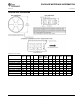
Table 2. Surface-Mount Ceramic Capacitors Selection Guide
2.2μF Surface-Mount Ceramic
Manufacturer Part Number
Tokin 1E225ZY5U-C203
Murata GRM42-6Y5V225Z16
4.7μF Surface-Mount Ceramic
Tokin 1E475ZY5U-C304
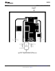
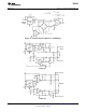
REVERSE CURRENT PATH
The P-channel Pass transistor used in the LM4140 has an inherent diode connected between the V
IN
and V
REF
pins (see diagram below).
Forcing the output to voltages higher than the input, or pulling V
IN
below voltage stored on the output capacitor
by more than a V
be
, will forward bias this diode and current will flow from the V
REF
terminal to V
IN
. No damage to
the LM4140 will occur under these conditions as long as the current flowing into the output pin does not exceed
50mA.
ON/OFF OPERATION
The LM4140 is designed to quickly reduce both V
REF
and I
Q
to zero when turned-off. V
REF
is restored in less than
200μs when turned-on. During the turn-off, the charge across the output capacitor is discharged to ground
through internal circuitry.
The LM4140 is turned-off by pulling the enable input low, and turned-on by driving the input high. If this feature is
not to be used, the enable pin should be tied to the V
IN
to keep the reference on at all times (the enable pin must
not be left floating).
To ensure proper operation, the signal source used to drive the enable pin must be able to swing above and
below the specified high and low voltage thresholds which ensure an ON or OFF state (see LM4140
Electrical Charateristics).
The ON/OFF signal may come from either a totem-pole output, or an open-collector output with pull-up resistor to
the LM4140 input voltage. This high-level voltage may exceed the LM4140 input voltage, but must remain within
the Absolute Maximum Rating for the enable pin.
OUTPUT ACCURACY
Like all references, either series or shunt, the after assembly accuracy is made up of primarily three components:
initial accuracy itself, thermal hysteresis and effects of the PCB assembly stress.
LM4140 provides an excellent output initial accuracy of 0.1% and temperature coefficient of 6ppm/°C (B Grade).
For best accuracy and precision, the LM4140 junction temperature should not exceed 70°C.
The thermal hysteresis curve on this datasheet are performance characteristics of three typical parts selected at
random from a sample of 40 parts.
Parts are mounted in a socket to minimize the effect of PCB's mechnical expansion and contraction. Readings
are taken at 25°C following multiple temperature cycles to 0°C and 70°C. The labels on the X axis of the graph
indicates the device temperature cycle prior to measurement at 25°C.
Copyright © 2000–2013, Texas Instruments Incorporated Submit Documentation Feedback 11
Product Folder Links: LM4140