
Datasheet


Table Of Contents
- Features (LM4121-1.2)
- Applications
- Description
- Absolute Maximum Ratings
- Operating Range
- Electrical Characteristics LM4121-1.250V
- Electrical Characteristics LM4121-ADJ
- LM4121- (All Options) Typical Operating Characteristics
- LM4121-1.25 Typical Operating Characteristics
- LM4121-ADJ Typical Operating Characteristics
- Application Hints
- Revision History
LM4121
SNVS073C –APRIL 2000–REVISED APRIL 2013
www.ti.com
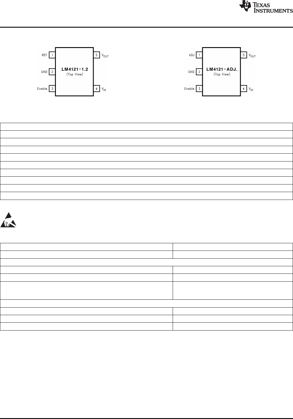
Connection Diagrams
Figure 2. SOT23-5 Surface Mount Package Figure 3. SOT23-5 Surface Mount Package
Table 1. SOT-23 Package Marking Information
(1)
Field Information
First Field:
R = Reference
Second and third Field:
19 = 1.250V Voltage Option
20 = Adjustable
Fourth Field:
A-B = Initial Reference Voltage Tolerance
A = ±0.2%
B = ±0.5%
(1) Only four fields of marking are possible on the SOT-23's small surface. This table gives the meaning of the four fields.
These devices have limited built-in ESD protection. The leads should be shorted together or the device placed in conductive foam
during storage or handling to prevent electrostatic damage to the MOS gates.
Absolute Maximum Ratings
(1)(2)
Maximum Voltage on input or enable pins −0.3V to 14V
Output Short-Circuit Duration Indefinite
Power Dissipation (T
A
= 25°C)
(3)
:
DBV0005B package − θ
JA
280°C/W
Power Dissipation 350 mW
ESD Susceptibility
(4)
Human Body Model 2 kV
Machine Model 200V
Lead Temperature:
Soldering, (10 sec.) +260°C
Vapor Phase (60 sec.) +215°C
Infrared (15 sec.) +220°C
(1) “Absolute Maximum Ratings” indicate limits beyond which damage to the device may occur. Operating Ratings indicate conditions for
which the device is intended to be functional, but do not ensure specific performance limits. For ensured specifications and test
conditions, see Electrical Characteristics - LM4121-1.250V and Electrical Characteristics - LM4121-ADJ tables. The ensured
specifications apply only for the test conditions listed. Some performance characteristics may degrade when the device is not operated
under the listed test conditions.
(2) If Military/Aerospace specified devices are required, please contact the Texas Instruments Sales Office/ Distributors for availability and
specifications.
(3) Without PCB copper enhancements. The maximum power dissipation must be de-rated at elevated temperatures and is limited by T
JMAX
(maximum junction temperature), θ
J-A
(junction to ambient thermal resistance) and T
A
(ambient temperature). The maximum power
dissipation at any temperature is: PDiss
MAX
= (T
JMAX
− T
A
)/θ
J-A
up to the value listed in the Absolute Maximum Ratings.
(4) The human body model is a 100 pF capacitor discharged through a 1.5 kΩ resistor into each pin. The machine model is a 200 pF
capacitor discharged directly into each pin.
2 Submit Documentation Feedback Copyright © 2000–2013, Texas Instruments Incorporated
Product Folder Links: LM4121