
User manual

www.ti.com
Controlling the Evaluation Board
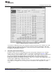
5.2 Direct Access to Registers
Controls on the frame Direct Access allows you to read/write from/to the chip registers manually. Enter the
register address to the Addr field and choose the binary value by clicking on the Data bits 7...0 and write
the selected value to the chip register by clicking on the Store button. Note that after clicking the Store
button all the register values will be read back automatically. Disable the automatic read by unchecking
Auto Write checkbox. Enter the register address to the Addr field and click the Read button to read the
specific register. The result will be displayed in the Data field in binary format.
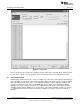
5.3 Control Signals
Buttons Enable, R_EN, G_EN, B_EN and PWM are used to manipulate input pins of the LM3549. Button
Fault Status is used to read status of FAULT pin. Pin value appears to value bar beside the button.
Setting Enable button high puts LM3549 to standby mode. I2C registers can be read and written in
standby mode but buck-boost converter and LED drivers are off. Setting Enable button low sets LM3549
to shutdown mode.
When device is on the standby mode LEDs can be turned on one at the time by clicking R_EN, G_EN or
B_EN. Even if two or more buttons are turned high at the same time, only the LED that was set high first
will be on.
Generation of special sequence of R, G and B signals can be enabled/disabled by checking/unchecking
Enable sequence checkbox. Period of the sequence is about 60 Hz and is similar to that described in the
LM3549 High Power Sequential LED Driver Data Sheet (SNVS640). Note that clicking on one of the
R_EN, G_EN, B_EN button will disable sequence generation automatically.
PWM generation can be enabled by dragging PWM track bar on bottom of the window. PWM frequency is
about 7.6kHz.
5.4 EEPROM Programming
Desired default register values can be stored to EEPROM. These values are always read back to registers
when Enable button is set from low to high. Keep the Enable button on and set all x_EN buttons off and
uncheck Enable sequence box. Write suitable values to all user registers. Set VDD to 5.0V and click on
the Store User Registers to EEPROM button. Set the Enable button off and back to on. Read all registers
by pressing the ReadAll button and verify that the values match with the stored values.
5.5 Fault LED
LED D4 is connected to LM3549's open drain fault output. If LM3549 detects any fault conditions e.g. LED
short or LED open it pulls the fault output low and turns on the fault LED. LM3549 has a fault register
which indicates what fault has occurred. Reading the fault register reset it's state and also reset the fault
output to high-z state. Different fault conditions are described in the LM3549 High Power Sequential LED
Driver Data Sheet (SNVS640).
7
SNVA443A–August 2010–Revised April 2013 AN-2062 LM3549 Evaluation Kit
Submit Documentation Feedback
Copyright © 2010–2013, Texas Instruments Incorporated