
User manual

Connecting the Evaluation Board to a Computer
www.ti.com
The onboard microcontroller has USB interface to communicate with PC. Connect evaluation board to PC
with USB cable. Evaluation software is used to control LM3549’s logic inputs and to use the I2C interface.
Evaluation software setup and use are described in the following sections
LM3549 evaluation board has three high current LEDs. These LED's are very bright even with minimum
current setting. Never look straight into the LEDs. This can damage your eyes! It is good practice to
always cover the LEDs with something to avoid looking straight into them.
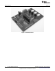
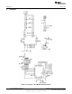
3.1 Connector Listing
• J1 - USB connector. Use this to connect the LM3549 to your PC.
• VIO - selector for digital logic levels. There should be a shunt in 3.3V position.
• X1- power supply connector. VDD terminal can be used to supply LM3549 input voltage from external
power supply. VIOX terminal can be used to connect external voltage for the digital signals.
• Connector for microcontroller programming is used to program the on-board microcontroller. This has
no user functions and needs to always be unconnected.
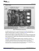
• P2 - P2 pin rail is used to connect on-board microcontroller to LM3549 digital lines. If you want to
connect LM3549 to your own system, shunts can be removed and your system can be connected to
the right side pins of the P2 pin rail.
• J3, J4 and J5 - LED disconnecting jumpers. These can be used to disconnect the LEDs from LM3549
LED outputs. This can be used to test the fault detection or to measure LED currents.
• P1 - Connector for VOUT and LED outputs. This can be used to connect external LEDs to the LM3549
evaluation board.
4 Connecting the Evaluation Board to a Computer
1. Check that the jumpers on the evaluation board are on wanted positions.
2. Connect external power supply to the evaluation board or, if evaluation board is to be powered form
USB port, set shunt to VDD position of the P2 pin rail.
3. Connect the USB board to your computer using a USB cable
4. Start the evaluation software LM3549.exe
5. Evaluation software may prompt you to update firmware of the LM3549 evaluation board. If it does
click ok and wait until update is completed.
6. Status bar at the center of the bottom row should say "OK" on green background. This indicates that
I2C interface between microcontroller and LM3549 is working correctly.
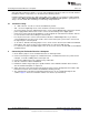
7. The evaluation kit is now fully up and running and the device can be controlled through the PC
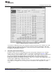
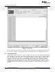
software. Figure 3 shows the evaluation software user interface (Control Panel).
4
AN-2062 LM3549 Evaluation Kit SNVA443A–August 2010–Revised April 2013
Submit Documentation Feedback
Copyright © 2010–2013, Texas Instruments Incorporated