
User manual

www.ti.com
Hardware Set-Up
3 Hardware Set-Up
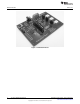
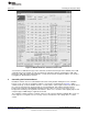
Figure 2. LM3549 Evaluation Board Setup
The LM3549 evaluation kit is based on a one board system, where the USB communication and
evaluation related components are assembled onto one board, (see Figure 2). The evaluation board was
designed especially for evaluation and, therefore, is not optimized for the smallest layout size. The
components are physically large to make changing component values easier.
LM3549 input voltage VDD can be supplied from the USB port or by connecting an external power supply
to the X1 connector. If voltage is supplied from USB port shunt needs to be placed on the VDD position of
P2 pin rail. If external power supply is used this shunt needs to be removed. USB port's maximum output
current is 500mA. This is not enough to drive the LEDs with maximum output current but can be used to
test functionality of the LM3549.
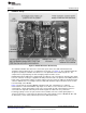
Figure 2 shows how to setup the LM3549 evaluation board. This configuration uses onboard
microcontroller to control the LM3549’s logic inputs. If one wishes to use external source to drive the
control signals, control signal jumpers needs to be removed and external control signals needs to be
connected to the right side of the P2 pin rail. Control signals are labeled for easy connection.
I
2
C interface pull-up resistors are placed on the microcontroller side of the control signal jumpers. If
external I
2
C interface is connected to the board it needs to have pull-up resistors. LM3549 I2C ID is 36h
(in 7bit format) -> write = 6Ch (8-bit format) and read = 6Dh (8-bit format)
3
SNVA443A–August 2010–Revised April 2013 AN-2062 LM3549 Evaluation Kit
Submit Documentation Feedback
Copyright © 2010–2013, Texas Instruments Incorporated