
Datasheet


Table Of Contents
ACC_PWR
GND
VCC
ACC_DET
A1
B1
C1
A2
B2
C2
LM34902/4
R1
POK
R2
C1 C2
R4
ENABLE
C3
www.ti.com
Evaluation Module Schematic
4 Evaluation Module Schematic
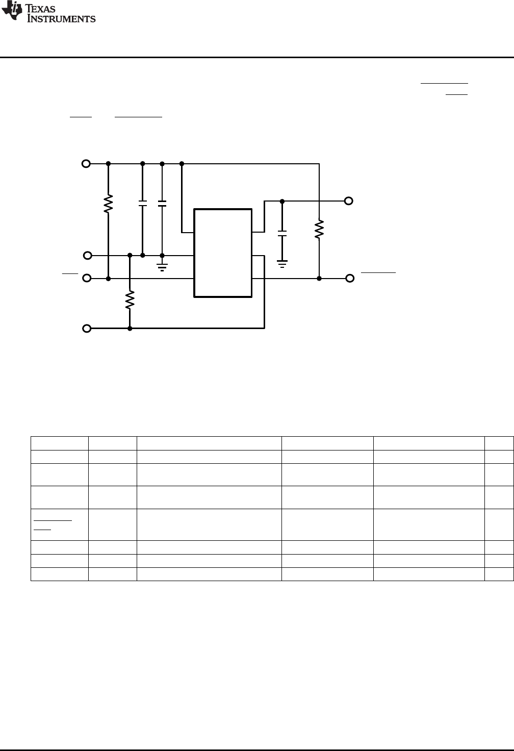
The schematic of the evaluation module is shown in Figure 2. Note that ENABLE and ACC_DET default to
their off-states if left open-circuited in this implementation. An active-low open-drain output (POK) provides
an indication of switch status to the CPU. As shown in Figure 2, the module provides pullup resistors to
VCC for POK and ACC_DET and a pulldown resistor to GND for ENABLE.
Figure 2. Evaluation Module Schematic
5 Evaluation Module Bill of Materials
Designator Value Description Manufacturer Part Number Qty
C1, C2 22 µF Ceramic, 22µF, X5R, 10V, 10%, 0805 Taiyo Yuden LMK212BJ226MG-T 2
C3 4.7 µF Ceramic, 4.7µF, X5R, 25V, 10%, Murata GRM21BR61E475KA12L 1
0805
VCC, Test Point, TH, Miniature, Red Keystone Electronics 5000 2
ACC_PWR
ENABLE, Test Point, TH, Miniature, White Keystone Electronics 5002 3
ACC_DET,
POK
GND Test Point, TH, Miniature, Black Keystone Electronics 5001 1
R1, R2, R4 220k Resistor, 220k ohm, 1%, 0.1W, 0603 Vishay-Dale CRCW0603220KFKEA 3
U1 500mA Current Limited Power Switch Texas Instruments LM34904 1
3
SNVU156A–July 2012–Revised May 2013 AN-2266 LM34902/4 Current Limited Power Switch Evaluation Module
Submit Documentation Feedback
Copyright © 2012–2013, Texas Instruments Incorporated