
User manual

Typical Waveforms
www.ti.com
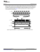
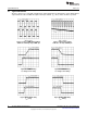
16 Typical Waveforms
All curves taken at V
IN
= 48V with configuration in typical application for driving twelve power LEDs with six
output channels active and 200 mA output current per channel. T
A
= 25°C, unless otherwise specified.
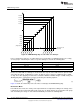
Figure 15. Direct PWM Dimming Mode Figure 16. DC Interface Mode
250Hz 50% dimming duty at DIMn pin 10Hz 3V to 2V ramp at DIMn pin
Figure 17. PWM dimming Figure 18. PWM dimming
I
OUTn
delay at V
DIMn
rising I
OUTn
delay at V
DIMn
falling
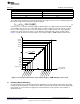
Figure 19. I
OUTn
ch-ch delay Figure 20. I
OUTn
ch-ch delay
I
OUTn
rising I
OUTn
falling
16
AN-2255 LM3463 Evaluation Board SNVA642A–May 2012–Revised May 2013
Submit Documentation Feedback
Copyright © 2012–2013, Texas Instruments Incorporated