
User manual

Input Data Code
(Decimal)
3/256
PWM dimming duty
4/256
5/256
0
6/256
3
2
4
1
5
254
253
255
252
0
256/256
251
255/256
254/256
253/256
252/256
2/256
(Skipped)1/256
PWM Dimming Control
www.ti.com
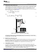
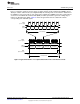
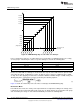
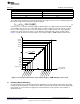
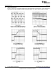
Figure 10. PWM dimming duty vs code value of a data byte
In the serial interface mode, the six output channels are grouped into four individual groups. The on duty
of each group is controlled by the value of a specific data byte as listed in the following table:
Output channel Data byte
CH0, CH1 BYTE1
CH2, CH3 BYTE2
CH4 BYTE3
CH5 BYTE4
Because the data width of a data byte is fixed to 8 bits, the step size of the LED current is equal to 1/256
of the full scale current. To allow the use of 0% on duty, the steps 1 and 2 are combined to give a 2/256
on duty. Thus either applying a hexadecimal code 001h or 002h the LM3463 will give a 2/256 on duty. The
dimming duty in the serial interface mode is governed by the following equation:
(5)
Figure 10 shows the relationship of the code value of a data byte and PWM dimming duty.
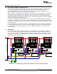
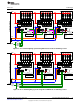
DC Interface Mode
In the DC interface mode, the on duty of the output channels are adjusted according to the voltage on the
terminals TP12, TP14, TP16 and TP20. In this mode, the six output channels are grouped into four groups
and controlled by the voltage on four terminals individually as listed in the following table:
12
AN-2255 LM3463 Evaluation Board SNVA642A–May 2012–Revised May 2013
Submit Documentation Feedback
Copyright © 2012–2013, Texas Instruments Incorporated