
User manual

+
-
5 P$
40 k:
Rectified AC
BIAS
AC
AC
LM3450A
C22
C23
R34
R36
R12
R14
R15
Q1
R5
R7
+
-
V
SEN
I
SEN
HOLD
R45
Q11
R61
D17
R44
NTC
GND
www.ti.com
Design Information
Input Capacitance
The input capacitor of the flyback (C1), also called the PFC capacitor, has to be able to provide energy
during the worst-case switching period at the peak of the AC input. C1 should be a high frequency, high
stability capacitor (usually a metallized film capacitor, either polypropylene or polyester) with an AC rating
equal to the maximum input voltage. C1 should also have a DC voltage rating exceeding the maximum
peak input voltage + half of the peak to peak input voltage ripple specification. The minimum required
input capacitance is calculated given the same ripple specification:
(19)
Output Capacitance
Since the LM3450A is a power factor controller, C1 is minimized and the output capacitor (C11) serves as
the main energy storage device. C11 should be a high quality electrolytic capacitor that can tolerate the
large current pulses associated with CRM operation. The voltage rating should be at least 25% greater
than the regulated output voltage and, given the desired voltage ripple, the minimum output capacitance is
calculated:
(20)
Definitions
Δv
IN-PK
– Peak Input Voltage Switching Ripple
Δv
OUT
– Nominal Output Voltage Ripple
Δv
CC
– Nominal Primary Bias Ripple
V
CC
– Primary Bias Capacitance
n
AUX
– Output to Auxiliary Turns Ratio
N
A
– Number of Auxiliary Turns
f
2L
– Twice Line Frequency
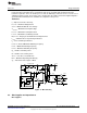
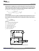
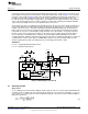
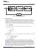
Figure 14. Dynamic Hold Circuit with Thermal Protection
15
SNVA485B–June 2011–Revised May 2013 AN-2150 LM3450A Evaluation Board
Submit Documentation Feedback
Copyright © 2011–2013, Texas Instruments Incorporated