
User manual

Circuit Operation With Reverse Phase Dimmer
www.ti.com
8 Circuit Operation With Reverse Phase Dimmer
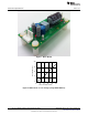
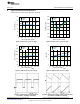
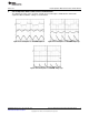
The circuit operation was also verified using a reverse phase dimmer and waveforms captured at different
dimmer settings are shown below:
Figure 16. Reverse phase circuit at full brightness Figure 17. Reverse phase circuit at 90° firing angle
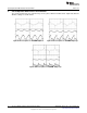
Figure 18. Reverse phase circuit at 135° firing angle
6
AN-2127 LM3448 A19 Edison Retrofit Evaluation Board SNOA559B–October 2011–Revised May 2013
Submit Documentation Feedback
Copyright © 2011–2013, Texas Instruments Incorporated