
User manual

t
I
in
(t)
0
Potential Misfire
Triac Fires Æ Inrush Spike
Design Calculations
www.ti.com
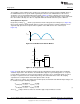
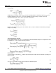
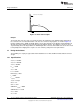
Figure 35. Inrush Current Spike
Damper
The inrush spike can also excite a resonance between the input filter of the TRIAC and the input filter of
the converter. The associated interaction can cause the current to ring negative, as shown in Figure 35,
thereby shutting off the TRIAC. A TRIAC damper can be placed between the dimmer and the EMI filter to
absorb some of the ringing energy and reduce the potential for misfires. The damper is also best sized
experimentally due to the large variance in TRIAC input filters. Resistors R5 and R6 can also be increased
to help dampen the ringing at the expense of some efficiency and power factor performance.
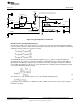
14 Design Calculations
The following is a step-by-step procedure with calculations for a 120V, 6.5W non-isolated buck converter
design.
14.1 Specifications
V
IN(MAX)
= 135VAC
V
IN(NOM)
= 120VAC
V
IN(MIN)
= 85VAC
P
OUT
= 6.5W
V
OUT
= 36V
I
LED
= 181mA
Efficiency,η = 80%
f
L
= 60Hz
f
SW(MAX)
=75kHz
T
S(MIN)
=13.33µs
Δv
OUT
= 1V
Δv
IN-PK
= 35V
SW FET V
DS(MAX)
= 600V
SW FET R
DS-ON
= 3.5Ω
V
f(D4)
= 0.8V
V
CC
= 12V
20
AN-2127 LM3448 A19 Edison Retrofit Evaluation Board SNOA559B–October 2011–Revised May 2013
Submit Documentation Feedback
Copyright © 2011–2013, Texas Instruments Incorporated