
User manual

L1
C6
D2
V+
LINE
NEUTRAL
L2
C2
C16
R4
R6
R5
C5
www.ti.com
Design Guide
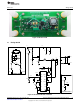
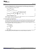
Figure 34. Input EMI Filter
Conducted
Figure 34 shows a typical filter used with this LM3448 flyback design. In order to conform to conducted
standards, a fourth order filter is implemented using inductors and "X" rated AC capacitors. If sized
properly, this filter design can provide ample attenuation of the switching frequency and lower order
harmonics contributing to differential noise. This combination of filter components along with any
necessary damping can easily provide a passing conducted EMI signature.
Radiated
Conforming to radiated EMI standards is much more difficult and is completely dependent on the entire
system including the enclosure. Reduction of dV/dt on switching edges and PCB layout iterations are
frequently necessary. Consult available literature and/or an EMI specialist for help with this. Several
iterations of component selection and layout changes may be necessary before passing a specific
radiated EMI standard.
Interaction with Dimmers
In general input filters and forward phase dimmers do not work well together. The TRIAC needs a
minimum amount of holding current to function. The converter itself is demanding a certain amount of
current from the input to provide to its output, and the input filter is providing or taking current depending
upon the dV/dt of the capacitors. The best way to deal with this problem is to minimize filter capacitance
and increase the regulated hold current until there is enough current to satisfy the dimmer and filter
simultaneously.
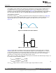
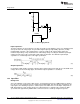
13.4 Inrush Limiting and Damping
Inrush
With a forward phase dimmer, a very steep rising edge causes a large inrush current every cycle as
shown in Figure 35. Series resistance (R5, R6) can be placed between the filter and the TRIAC to limit the
effect of this current on the converter and to provide some of the necessary holding current at the same
time. This will degrade efficiency but some inrush protection is always necessary in any AC system due to
startup. The size of R5 and R6 are best found experimentally as they provide attenuation for the whole
system.
19
SNOA559B–October 2011–Revised May 2013 AN-2127 LM3448 A19 Edison Retrofit Evaluation Board
Submit Documentation Feedback
Copyright © 2011–2013, Texas Instruments Incorporated