
User manual

R3
D7
Q1
R8
V+
C8
R22
D8
LM3448
6VCC
R1
V
CC
Design Guide
www.ti.com
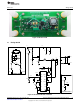
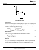
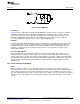
Figure 33. Bias Supply Circuit
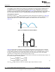
Input Capacitance
The input capacitors C1 and C10 have to be able to provide energy during the worst-case switching period
at the peak of the AC voltage input. They should be high frequency, high stability capacitors (usually
metallized film capacitors, either polypropylene or polyester) with an AC voltage rating equal to the
maximum input voltage. They should also have a DC voltage rating exceeding the maximum peak input
voltage plus half of the peak to peak input voltage ripple specification. The minimum required input
capacitance is calculated given the same ripple specification,
(27)
Output Capacitance
C3 should be a high quality electrolytic capacitor with a voltage rating greater than the specified LED stack
voltage. Given the desired voltage ripple, the minimum output capacitance is calculated,
(28)
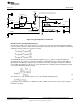
13.3 Input Filter
Background
Since the LM3448 is used for AC to DC systems, electromagnetic interference (EMI) filtering is critical to
pass the necessary standards for both conducted and radiated EMI. This filter will vary depending on the
output power, the switching frequencies, and the layout of the PCB. There are two major components to
EMI: differential noise and common-mode noise. Differential noise is typically represented in the EMI
spectrum below approximately 500kHz while common-mode noise shows up at higher frequencies.
18
AN-2127 LM3448 A19 Edison Retrofit Evaluation Board SNOA559B–October 2011–Revised May 2013
Submit Documentation Feedback
Copyright © 2011–2013, Texas Instruments Incorporated