
User manual

Design Guide
www.ti.com
Re-arranging the above equation results in R16 being calculated where C12 is typically chosen as value
around 470pF,
(12)
Additionally, the maximum on-time t
ON(MAX)
and corresponding minimum switching frequency f
SW(MIN)
and
maximum switching period T
S(MAX)
occur at the minimum peak input voltage. Using the previously
calculated inductor value, these values can now be calculated as,
(13)
Maximum and minimum duty cycles, D
MAX
and D
MIN
, will occur at the minimum and maximum peak input
voltages respectively,
(14)
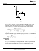
Switching MOSFET (SW FET)
Peak and RMS SW FET currents are calculated along with maximum SW FET power dissipation based on
the SW FET R
DS-ON
value using the following equations,
(15)
(16)
and,
(17)
Current Limit
The peak inductor current limit I
LIM
should be approximately 25% higher than the maximum operating peak
inductor current,
(18)
The sense resistor will need to be able to dissipate the maximum power,
(19)
16
AN-2127 LM3448 A19 Edison Retrofit Evaluation Board SNOA559B–October 2011–Revised May 2013
Submit Documentation Feedback
Copyright © 2011–2013, Texas Instruments Incorporated