
User manual

COFF
R16
C12
V
CC
www.ti.com
Design Guide
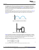
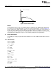
Inductor ripple current will need to be specified by the user based on desired EMI performance, inductor
size and other operating conditions. The following equations show how to calculate for maximum and
minimum inductor ripple currents respectively by basing the ripple (i.e.Δi
L(%)
as a percentage of maximum
peak inductor currents,
(6)
It is recommended that this buck converter design operate in CCM over the full range of operating peak
input voltages, and so the minimum inductor peak current at V
IN-PK(MIN)
should not go below zero,
(7)
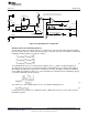
The inductor value can be calculated based on the minimum on-time, LED output voltage and the
specified inductor ripple current Δi
L-PK(VIN-PK-MAX)
at the maximum peak input voltage as described below,
(8)
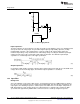
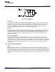
COFF Current Source
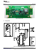
The current source used to establish the constant off-time is shown in Figure 32.
Figure 32. COFF Current Source Circuit
Capacitor C12 will be charged with current from the V
CC
supply through resistor R16. The COFF pin
threshold will therefore be tripped based on the following capacitor equation,
(9)
where,
(10)
Solving for off-time t
OFF
results in,
(11)
15
SNOA559B–October 2011–Revised May 2013 AN-2127 LM3448 A19 Edison Retrofit Evaluation Board
Submit Documentation Feedback
Copyright © 2011–2013, Texas Instruments Incorporated