
User manual


R15
C15
R2
R7
V+
LM3448
11 FLTR2
C14
V
INJECT
t
V
INJECT
Design Guide
www.ti.com
13.1 Buck Converter
The following section explains how to design a non-isolated buck converter using the LM3448. Refer to
the LM3448 datasheet for specific details regarding the function of the LM3448 device. All reference
designators refer to the Evaluation Board Schematic in Figure 25 unless otherwise noted. The circuit
operates in open-loop based on a constant off-time that is set by selecting appropriate circuit components.
Like an incandescent lamp, the driver is compatible with both forward and reverse phase dimmers.
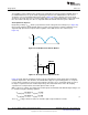
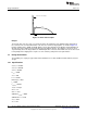
AC-Coupled Line Injection
By injecting a voltage V
INJECT
which is proportional to the line voltage into the FLTR2 pin (see Figure 26),
input current shaping is obtained which improves power factor performance. By AC-coupling the V
INJECT
signal through capacitor C14, improved line-regulation of the LED current is also achieved (see
Figure 27).
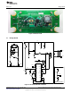
Figure 26. FLTR2 Waveform with No Dimmer
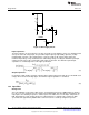
Figure 27. AC-Coupled Line-Injection Circuit
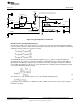
Figure 28 shows how line shaping of the input current is implemented. Peak voltage at the FLTR2 pin
should be kept below 1.25V otherwise current limit will be tripped. A good starting point is to set up the
resistor divider consisting of resistors R2, R7 and R15 to provide a V
INJECT
peak input voltage of 1.0V at
the input of capacitor C14 at the nominal input voltage. Recommended values for the AC-coupling
capacitor C14 is 0.47µF and for the FLTR2 capacitor C15 is 0.1µF.
With a 1.0V V
INJECT
voltage, the voltage at the FLTR2 pin at the maximum and minimum input voltages can
be calculated using the following equations,
(1)
These V
FLTR2
voltages will be used later to determine ripple and peak inductor currents.
12
AN-2127 LM3448 A19 Edison Retrofit Evaluation Board SNOA559B–October 2011–Revised May 2013
Submit Documentation Feedback
Copyright © 2011–2013, Texas Instruments Incorporated