
User manual

LED +
LED - LINE
NEUTRAL
J10
J5
TP4
TP3
TP1
TP2
Demo Board Wiring Overview
www.ti.com
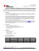
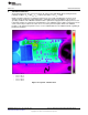
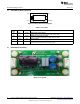
11 Demo Board Wiring Overview
Figure 22. Wiring Connection Diagram
Table 2. Test Points
Test Name I/O Description
Point
TP3 LED + Output LED Constant Current Supply
Supplies voltage and constant-current to anode of LED string.
TP4 LED - Output LED Return Connection (not GND)
Connects to cathode of LED string. Do NOT connect to GND.
TP1 LINE Input AC Line Voltage
Connects directly to AC line or output of TRIAC dimmer of a 120VAC system.
TP2 NEUTRAL Input AC Neutral
Connects directly to AC neutral of a 120VAC system.
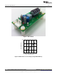
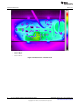
12 Demo Board Assembly
Figure 23. Top View
10
AN-2127 LM3448 A19 Edison Retrofit Evaluation Board SNOA559B–October 2011–Revised May 2013
Submit Documentation Feedback
Copyright © 2011–2013, Texas Instruments Incorporated