
Datasheet


Table Of Contents
- Using the LM3447-A19-120VEVM
- 1 Introduction
- 2 Description
- 3 Electrical Performance Specifications
- 4 Schematic
- 5 Test Setup
- 6 Test Procedure
- 7 Performance Data and Typical Characteristic Curves
- 7.1 Efficiency
- 7.2 Power Factor
- 7.3 Line Regulation
- 7.4 Input Current THD
- 7.5 Output Ripple
- 7.6 Switch Node Voltage Valley Switching
- 7.7 Triac Dimmer LED Current vs Conduction Angle
- 7.8 Turn-On Angle vs Input Power
- 7.9 Input/Output Current and Line Voltage Waveforms vs. Dimmer Setting
- 7.10 Current Sense Waveform
- 7.11 LED Open and Short Circuit Waveforms
- 7.12 EMI Plot
- 7.13 Transformer Specification
- 8 EVM Assembly Drawing and PCB Layout
- 9 List of Materials
- Important Notices
Test Setup
www.ti.com
5 Test Setup
5.1 Test Equipment
Voltage Source: 105 VRMS to 135 VRMS isolated AC source PCR500LA (KIKUSUI)
Multimeters: Agilent 34401A
Power Meter: PM1000 Digital Power Meter (Voltech)
Output Load: 9 LEDs in series (VF = 3.2 V at 350 mA per LED)
Oscilloscope: TDS3045C (TEKTRONIX)
Operating Temperature: 25°C
Recommended Wire Gauge: 18 AWG not more than two feet long
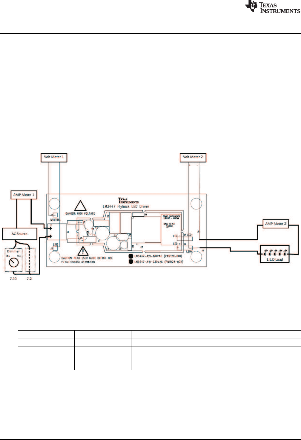
5.2 Recommended Test Setup
Figure 2. LM3447-A19-120VEVM Recommended Test Set Up
5.3 List of Test Points
Table 2. Test Points Functions
TEST POINTS NAME DESCRIPTION
TP1 Neutral 120 V
AC
neutral connection
TP2 Line 120 V
AC
line voltage
J8 LED+ LED anode connection
J9 LED- LED cathode connection
6
LM3447-A19-120VEVM is a Phase-Dimmable, Primary-Side Regulated LED SLUU937–May 2012
Driver
Submit Documentation Feedback
Copyright © 2012, Texas Instruments Incorporated