
Datasheet


Table Of Contents
- Using the LM3447-A19-120VEVM
- 1 Introduction
- 2 Description
- 3 Electrical Performance Specifications
- 4 Schematic
- 5 Test Setup
- 6 Test Procedure
- 7 Performance Data and Typical Characteristic Curves
- 7.1 Efficiency
- 7.2 Power Factor
- 7.3 Line Regulation
- 7.4 Input Current THD
- 7.5 Output Ripple
- 7.6 Switch Node Voltage Valley Switching
- 7.7 Triac Dimmer LED Current vs Conduction Angle
- 7.8 Turn-On Angle vs Input Power
- 7.9 Input/Output Current and Line Voltage Waveforms vs. Dimmer Setting
- 7.10 Current Sense Waveform
- 7.11 LED Open and Short Circuit Waveforms
- 7.12 EMI Plot
- 7.13 Transformer Specification
- 8 EVM Assembly Drawing and PCB Layout
- 9 List of Materials
- Important Notices
C2, C4: 305Vac, X2 class
R1: Fusible Resistor
EMI Filter and Snubber Circuit
Hardware and Fiducials
1
1
1
Not populated
90VAC
to
135VAC
Output: 28V to 32V
Notes:
J1
J2
J3
J4
J5
R1
22
MOV1
140VAC, 12J
C4
33nF
R15
R16
D2
HD04
R4
430k
R3
430k
D7
3.9V
Q1
450V
R2
470
C3
0.22uF
R5
100
R8
5.1k
C8
2.2uF, 25V
D5
BAV19WS-TP
C9
22uF, 25V
Q2
650V
R11
0.2
D3
UFM15PL-TP
D1
160V, 400W
SMAJ160A
R9
220k
R10
23.7k
R7
10
D6
BAV19WS-TP
R12
280k
C10
0.1uF
R13
118k
C11
0.1uF
C12
10uF
D4
ES1D-13-F
R6
22k
C6
1uF, 50V
J6
J7
R14
10
SC1
SC2
SC3
SC4
J8
J9
1
2
3
4
5
6
7
8
9
10
T1
750813049
Wurth Electronics
1
VAC
2
TSNS
3
FTR1
4
FTR2
5
FF
6
INV
7
COMP
8
GND
9
ISNS
10
GATE
11
VCC
12
AUX
13
HOLD
14
BIAS
U1
LM3447MT
LM3447MT
C1
0.1uF
+
C5
470uF
L1
3.3mH
L2
3.3mH
RT1
100k
F1
250VAC, 2A
C2
10nF
C7
1000pF
LED+
LED-
www.ti.com
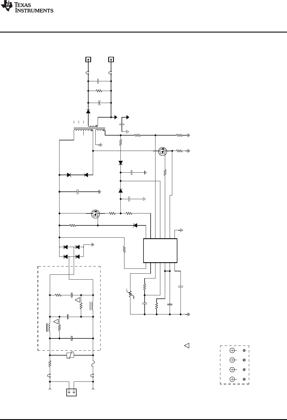
Schematic
4 Schematic
Figure 1. LM3447-A19-120VEVM Schematic
5
SLUU937–May 2012 LM3447-A19-120VEVM is a Phase-Dimmable, Primary-Side Regulated LED
Driver
Submit Documentation Feedback
Copyright © 2012, Texas Instruments Incorporated