
Datasheet


Table Of Contents
- Using the LM3447-A19-120VEVM
- 1 Introduction
- 2 Description
- 3 Electrical Performance Specifications
- 4 Schematic
- 5 Test Setup
- 6 Test Procedure
- 7 Performance Data and Typical Characteristic Curves
- 7.1 Efficiency
- 7.2 Power Factor
- 7.3 Line Regulation
- 7.4 Input Current THD
- 7.5 Output Ripple
- 7.6 Switch Node Voltage Valley Switching
- 7.7 Triac Dimmer LED Current vs Conduction Angle
- 7.8 Turn-On Angle vs Input Power
- 7.9 Input/Output Current and Line Voltage Waveforms vs. Dimmer Setting
- 7.10 Current Sense Waveform
- 7.11 LED Open and Short Circuit Waveforms
- 7.12 EMI Plot
- 7.13 Transformer Specification
- 8 EVM Assembly Drawing and PCB Layout
- 9 List of Materials
- Important Notices
EVM Assembly Drawing and PCB Layout
www.ti.com
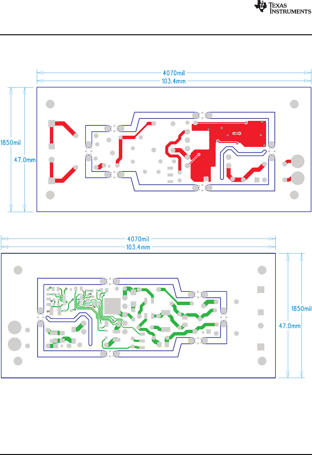
8 EVM Assembly Drawing and PCB Layout
The following figures (Figure 29 through Figure 32) show the design of the LM3447EVM-128 printed
circuit board.
Figure 29. LM3447-A19-120VEVM Top Layer Copper (top view)
Figure 30. LM3447-A19-120VEVM Bottom Layer Copper (bottom view)
22
LM3447-A19-120VEVM is a Phase-Dimmable, Primary-Side Regulated LED SLUU937–May 2012
Driver
Submit Documentation Feedback
Copyright © 2012, Texas Instruments Incorporated