
User manual

R15 C15
FLTR2
R2
R7
DIM
R9
COFF
C13
R1
R3
D7
Q1
R8
ASNS
FLTR1
DIM
COFF
FLTR2
BLDR
VCC
GND
GATE
ISNS
LM3445
1
2
3
4
5
10
9
8
7
6
V+
C8
V
CC
R22
D8
R12
R14
+
VLED+
VLED±
L1
C6
D2
V+
LINE NEUTRAL
LINE EMI FILTER
Q4
D4
C4
C3
V
CC
COFF
R16
C12
L2
C2
C
OFF
Current Source
C1
L3
C5
R4
C10
C14
RT1
F1
R6
R24
R5C9
D1
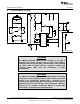
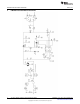
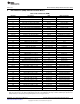
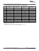
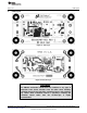
Simplified LM3445 Schematic
www.ti.com
3 Simplified LM3445 Schematic
WARNING
The LM3445 evaluation boards have no isolation or any type of
protection from shock. Caution must be taken when handling
evaluation board. Avoid touching evaluation board, and removing
any cables while evaluation board is operating. Isolating the
evaluation board rather than the oscilloscope is highly
recommended.
WARNING
This LM3445 evaluation PCB is a non-isolated design. The ground
connection on the evaluation board is NOT referenced to earth
ground. If an oscilloscope ground lead is connected to the
evaluation board ground test point for analysis, and AC power is
applied, the fuse (F1) will fail open. The oscilloscope should be
powered via an isolation transformer before an oscilloscope
ground lead is connected to the evaluation board.
2
AN-2061 LM3445 A19 Edison Retrofit Evaluation Board SNVA442C–June 2010–Revised May 2013
Submit Documentation Feedback
Copyright © 2010–2013, Texas Instruments Incorporated