
User manual

R15 C11
FLTR2
R2
R7
DIM
R9
COFF
ASNS
FLTR1
DIM
COFF
FLTR2
BLDR
VCC
GND
GATE
ISNS
LM3445
1
2
3
4
5
10
9
8
7
6
V+
t
V
FLTR2
Circuit Analysis and Explanations
www.ti.com
18 Circuit Analysis and Explanations
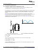
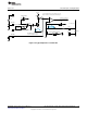
18.1 Injecting Line Voltage into Filter-2 (Achieving PFC > 0.95)
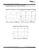
If a small portion (750mV to 1.00V) of line voltage is injected at FLTR2 of the LM3445, the circuit is
essentially turned into a constant power flyback as shown in Figure 34.
The LM3445 works as a constant off-time controller normally, but by injecting the 1.0V rectified AC voltage
into the FLTR2 pin, the on-time can be made to be constant. With a DCM Flyback, Δi needs to increase
as the input voltage line increases. Therefore a constant on-time (since inductor L is constant) can be
obtained.
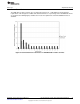
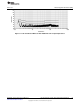
By using the line voltage injection technique, the FLTR2 pin has the voltage wave shape shown in
Figure 35 on it with no TRIAC dimmer in-line. Voltage at V
FLTR2
peak should be kept below 1.25V. At 1.25V
current limit is tripped. C11 is small enough not to distort the AC signal but adds a little filtering.
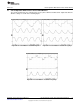
Although the on-time is probably never truly constant, it can be observed in Figure 36 how (by adding the
rectified voltage) the on-time is adjusted.
Figure 34. Line Voltage Injection Circuit Figure 35. FLTR2 Waveform with No Dimmer
For this evaluation board, the following resistor values are used:
R2 = R7 = 309kΩ
R15 = 3.48kΩ
Therefore the voltages observed on the FLTR2 pin will be as follows for listed input voltages:
For VIN = 90V
RMS
, V
FLTR2
= 0.71V
For VIN = 120V
RMS
, V
FLTR2
= 0.95V
For VIN = 135V
RMS
, V
FLTR2
= 1.07V
Using this technique, a power factor greater than 0.95 can be achieved without additional passive active
power factor control (PFC) circuitry.
26
AN-2034 LM3445 -120VAC, 8W Isolated Flyback LED Driver SNVA429C–August 2010–Revised May 2013
Submit Documentation Feedback
Copyright © 2010–2013, Texas Instruments Incorporated