
User manual

L1
C5
R4
V+
LINE
NEUTRAL
C6
L2
R6
R24
C9
R5
C2
RT1
D2
F1
Electromagnetic Interference (EMI)
www.ti.com
16 Electromagnetic Interference (EMI)
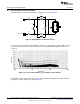
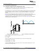
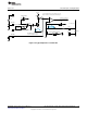
The EMI input filter of this evaluation board is configured as shown in Figure 29.
Figure 29. Input EMI Filter and Rectifier Circuit
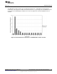
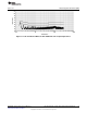
In order to get a quick estimate of the EMI filter performance, only the PEAK conductive EMI scan was
measured and the data was compared to the Class B conducted EMI limits published in FCC – 47,
section 15.
Figure 30. Peak Conductive EMI Scan per CISPR-22, Class B Limits
If an additional 33nF of input capacitance (that is, C6) is utilized in the input filter, the EMI conductive
performance is further improved as shown in Figure 31.
22
AN-2034 LM3445 -120VAC, 8W Isolated Flyback LED Driver SNVA429C–August 2010–Revised May 2013
Submit Documentation Feedback
Copyright © 2010–2013, Texas Instruments Incorporated