
User manual

www.ti.com
11 LED Current vs. Line Voltage Modified Circuits ....................................................................... 11
12 Power Factor vs. Line Voltage Original Circuit ........................................................................ 11
13 Power Factor vs. Line Voltage Modified Circuits ...................................................................... 11
14 Output Power vs. Line Voltage Original Circuit........................................................................ 12
15 Output Power vs. Line Voltage Modified Circuits ..................................................................... 12
16 Power MOSFET Drain Voltage Waveform (V
IN
= 120V
RMS
, 6 LEDs, I
LED
= 350mA)............................... 12
17 Current Sense Waveform (V
IN
= 120V
RMS
, 6 LEDs, I
LED
= 350mA) .................................................. 12
18 FLTR2 Waveform (V
IN
= 120V
RMS
, 6 LEDs, I
LED
= 350mA) ........................................................... 12
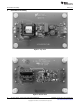
19 Top Layer................................................................................................................... 14
20 Bottom Layer............................................................................................................... 14
21 LED Current vs. Input Voltage (using Dimmer) ....................................................................... 18
22 Current Harmonic Performance vs. EN/IEC61000-3-2 Class C Limits............................................. 19
23 Forward Phase Circuit at Full Brightness .............................................................................. 20
24 Forward Phase Circuit at 90° Firing Angle............................................................................. 20
25 Forward Phase Circuit at 150° Firing Angle ........................................................................... 20
26 Reverse Phase Circuit at Full Brightness .............................................................................. 21
27 Reverse Phase Circuit at 90° Firing Angle............................................................................. 21
28 Reverse Phase Circuit at 150° Firing Angle ........................................................................... 21
29 Input EMI Filter and Rectifier Circuit .................................................................................... 22
30 Peak Conductive EMI Scan per CISPR-22, Class B Limits.......................................................... 22
31 Peak Conductive EMI Scan with Additional 33nF of Input Capacitance ........................................... 23
32 Top Side Thermal Scan .................................................................................................. 24
33 Bottom Side Thermal Scan............................................................................................... 25
34 Line Voltage Injection Circuit............................................................................................. 26
35 FLTR2 Waveform with No Dimmer ..................................................................................... 26
36 Typical Operation of FLTR2 Pin ........................................................................................ 27
List of Tables
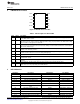
1 Pin Description 10 Pin VSSOP............................................................................................ 7
2 Wiring Connection .......................................................................................................... 9
3 Measured Efficiency and Line Regulation (6 LEDs, No TRIAC Dimmer) .......................................... 16
4 LED Current, Output Power Versus Number of LEDs for Various Circuit Modifications (V
IN
= 120 V
AC
, no
TRIAC Dimmer)............................................................................................................ 16
5 Measured Efficiency and Line Regulation Data (with TRIAC Dimmer)............................................. 17
2
AN-2034 LM3445 -120VAC, 8W Isolated Flyback LED Driver SNVA429C–August 2010–Revised May 2013
Submit Documentation Feedback
Copyright © 2010–2013, Texas Instruments Incorporated