
User manual

Experimental Results
www.ti.com
13 Experimental Results
The LED driver is designed to accurately emulate an incandescent light bulb and therefore behave as an
emulated resistor. The resistor value is determined based on the LED string configuration and the desired
output power. The circuit then operates in open-loop, with a fixed duty cycle based on a constant on-time
and constant off-time that is set by selecting appropriate circuit components. Like an incandescent lamp,
the driver is compatible with both forward and reverse phase dimmers.
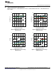
13.1 Non-Dimming Performance
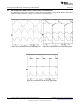
In steady state, the LED string voltage is measured to be 20.1 V and the average LED current is
measured as 365 mA. The 120 Hz current ripple flowing through the LED string was measured to be 182
mA
pk-pk
at full load. The magnitude of the ripple is a function of the value of energy storage capacitors
connected across the output port and the TRIAC firing angle. The ripple current can be reduced by
increasing the value of energy storage capacitor or by increasing the LED string voltage. With TRIAC
dimmers, the ripple magnitude is directly proportional to the input power and therefore reduces at lower
LED current.
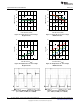
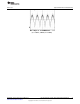
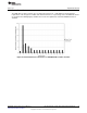
The LED driver switching frequency is measured to be close to the specified 78.5 kHz. The circuit
operates with a constant duty cycle of 0.28 and consumes near 9.2 W of input power. The driver steady
state performance for an LED string consisting of 6 series LEDs without using a TRIAC dimmer is
summarized in Table 3.
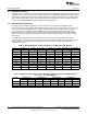
Table 3. Measured Efficiency and Line Regulation (6 LEDs, No TRIAC Dimmer)
V
IN
(V
RMS
) I
IN
(mA
RMS
) P
IN
(W) V
OUT
(V) I
LED
(mA) P
OUT
(W) Efficiency (%) Power Factor
89.98 64 5.44 19.24 222 4.27 78.5 94.7
95.03 67 6.03 19.40 244 4.73 78.5 94.8
100.00 70 6.62 19.55 267 5.22 78.8 94.9
104.97 73 7.24 19.69 291 5.73 79.1 95.0
110.03 76 7.90 19.83 315 6.25 79.1 95.0
115.00 78 8.55 19.95 340 6.78 79.3 95.1
120.05 81 9.21 20.06 365 7.32 79.5 95.1
125.02 83 9.84 20.14 389 7.83 79.6 95.0
129.99 85 10.44 20.22 412 8.33 79.8 94.9
135.04 86 11.02 20.29 433 8.79 79.7 94.8
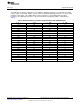
Table 4. LED Current, Output Power Versus Number of LEDs for Various Circuit Modifications
(V
IN
= 120 V
AC
, no TRIAC Dimmer)
# of LEDs Original Circuit
(1)
Modification A
(1)
Modification B
(1)
Modification C
(1)
I
LED
(mA) P
OUT
(W) I
LED
(mA) P
OUT
(W) I
LED
(mA) P
OUT
(W) I
LED
(mA) P
OUT
(W)
4 513 7.11 627 8.83 683 10.03 805 11.91
6 365 7.32 435 9.09 481 10.22 566 12.23
8 276 7.34 334 9.16 367 10.16 431 12.12
(1)
Original Circuit: R14 = 1.50Ω; Modification A: R14 = 1.20Ω; Modification B: R14 = 1.00Ω; Modification C: R14 = 0.75Ω
16
AN-2034 LM3445 -120VAC, 8W Isolated Flyback LED Driver SNVA429C–August 2010–Revised May 2013
Submit Documentation Feedback
Copyright © 2010–2013, Texas Instruments Incorporated