
User manual

1
4
3
2
10
7
8
9
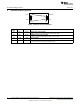
I
SNS
NC
GATE
NC
COFF
V
CC
NC
NC
5 6FILTER GND
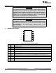
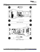
LM3444 Device Pin-Out
www.ti.com
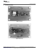
WARNING
The ground connection on the evaluation board is NOT referenced
to earth ground. If an oscilloscope ground lead is connected to the
evaluation board ground test point for analysis and AC power is
applied, the fuse (F1) will fail open. The oscilloscope should be
powered via an isolation transformer before an oscilloscope
ground lead is connected to the evaluation board.
WARNING
The LM3444 evaluation board should not be powered with an open
load. For proper operation, ensure that the desired number of LEDs
are connected at the output before applying power to the
evaluation board.
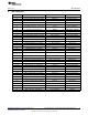
6 LM3444 Device Pin-Out
Table 1. Pin Description 10-Pin VSSOP
Pin # Name Description
1 NC No internal connection.
2 NC No internal connection.
3 NC No internal connection.
4 COFF OFF time setting pin. A user set current and capacitor connected from the output to this pin sets the constant
OFF time of the switching controller.
5 FILTER Filter input. A capacitor tied to this pin filters the error amplifier. Could also be used as an analog dimming
input.
6 GND Circuit ground connection.
7 ISNS LED current sense pin. Connect a resistor from main switching MOSFET source, ISNS to GND to set the
maximum LED current.
8 GATE Power MOSFET driver pin. This output provides the gate drive for the power switching MOSFET of the buck
controller.
9 V
CC
Input voltage pin. This pin provides the power for the internal control circuitry and gate driver.
10 NC No internal connection.
4
AN-2082 LM3444 -120VAC, 8W Isolated Flyback LED Driver SNVA454E–September 2010–Revised May 2013
Submit Documentation Feedback
Copyright © 2010–2013, Texas Instruments Incorporated