
User manual

R
SNS
PWM
I-LIM
1.27V
I
SNS
PGND
FILTER
1M
C
FILTER
1k
750 mV
125 ns
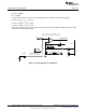
LEADING EDGE BLANKING
1V
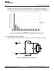
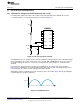
Nearly a constant on-
time as the line varies
The PWM reference increases
as the line voltage increases.
As line voltage increases, the voltage across the
inductor increases, and the peak current increases.
1V
D x LED Current
Circuit Analysis and Explanations
www.ti.com
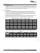
For this evaluation board, the following resistor values are used:
R2 = R7 = 309kΩ
R15 = 3.48kΩ
Therefore the voltages observed on the FILTER pin will be as follows for listed input voltages:
For VIN = 90V
RMS
, V
FILTER
= 0.71V
For VIN = 120V
RMS
, V
FILTER
= 0.95V
For VIN = 135V
RMS
, V
FILTER
= 1.07V
Using this technique, a power factor greater than 0.99 can be achieved without additional passive active
power factor control (PFC) circuitry.
Figure 25. Typical Operation of FILTER Pin
18
AN-2082 LM3444 -120VAC, 8W Isolated Flyback LED Driver SNVA454E–September 2010–Revised May 2013
Submit Documentation Feedback
Copyright © 2010–2013, Texas Instruments Incorporated