
User manual

t
V
FILTER
R15 C11
FILTER
R2
R7
COFF
NC
NC
NC
COFF
FILTER
NC
VCC
GND
GATE
ISNS
LM3444
1
2
3
4
5
10
9
8
7
6
V+
www.ti.com
Circuit Analysis and Explanations
16 Circuit Analysis and Explanations
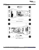
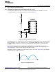
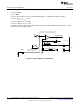
16.1 Injecting Line Voltage Into FILTER (Achieving PFC > 0.99)
If a small portion (750mV to 1.00V) of line voltage is injected at FILTER of the LM3444, the circuit is
essentially turned into a constant power flyback, as shown in Figure 23.
Figure 23. Line Voltage Injection Circuit
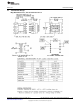
The LM3444 works as a constant off-time controller normally, but by injecting the 1.0V rectified AC voltage
into the FILTER pin, the on-time can be made to be constant. With a DCM Flyback, Δi needs to increase
as the input voltage line increases. Therefore a constant on-time (since inductor L is constant) can be
obtained.
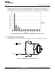
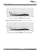
By using the line voltage injection technique, the FILTER pin has the voltage wave shape shown in
Figure 24 on it. Voltage at V
FILTER
peak should be kept below 1.25V. At 1.25V current limit is tripped. C11
is small enough not to distort the AC signal but adds a little filtering.
Although the on-time is probably never truly constant, it can be observed in Figure 25 how (by adding the
rectified voltage) the on-time is adjusted.
Figure 24. FILTER Waveform
17
SNVA454E–September 2010–Revised May 2013 AN-2082 LM3444 -120VAC, 8W Isolated Flyback LED Driver
Submit Documentation Feedback
Copyright © 2010–2013, Texas Instruments Incorporated