
User manual

Experimental Results
www.ti.com
13 Experimental Results
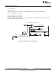
The LED driver is designed to accurately emulate an incandescent light bulb and therefore behave as an
emulated resistor. The resistor value is determined based on the LED string configuration and the desired
output power. The circuit then operates in open-loop, with a fixed duty cycle based on a constant on-time
and constant off-time that is set by selecting appropriate circuit components.
13.1 Performance
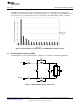
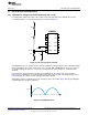
In steady state, the LED string voltage is measured to be 21.38 V and the average LED current is
measured as 357 mA. The 120 Hz current ripple flowing through the LED string was measured to be 170
mA
pk-pk
at full load. The magnitude of the ripple is a function of the value of energy storage capacitors
connected across the output port. The ripple current can be reduced by increasing the value of energy
storage capacitor or by increasing the LED string voltage.
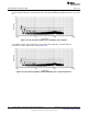
The LED driver switching frequency is measured to be close to the specified 79 kHz. The circuit operates
with a constant duty cycle of 0.28 and consumes 9.25 W of input power. The driver steady state
performance for an LED string consisting of 6 series LEDs is summarized in the following table.
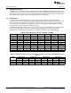
Table 2. Measured Efficiency and Line Regulation (6 LEDs)
V
IN
(V
RMS
) I
IN
(mA
RMS
) P
IN
(W) V
OUT
(V) I
LED
(mA) P
OUT
(W) Efficiency (%) Power Factor
90 60 5.37 20.25 216 4.38 81.6 0.9970
95 63 5.95 20.47 238 4.87 81.8 0.9969
100 66 6.57 20.67 260 5.38 81.9 0.9969
105 69 7.23 20.86 285 5.94 82.1 0.9969
110 72 7.89 21.05 309 6.50 82.3 0.9968
115 75 8.59 21.23 334 7.09 82.5 0.9967
120 77 9.25 21.38 357 7.65 82.7 0.9965
125 80 9.94 21.53 382 8.23 82.8 0.9961
130 82 10.62 21.68 406 8.80 82.9 0.9957
135 84 11.26 21.80 428 9.34 83.0 0.9950
Table 3. LED Current, Output Power versus Number of LEDs for Various Circuit Modifications (V
IN
= 120 V
AC
)
# of LEDs Original Circuit
(1)
Modification A
(1)
Modification B
(1)
Modification C
(1)
I
LED
(mA) P
OUT
(W) I
LED
(mA) P
OUT
(W) I
LED
(mA) P
OUT
(W) I
LED
(mA) P
OUT
(W)
4 508 7.57 624 9.55 710 11.05 835 13.24
6 357 7.65 440 9.58 500 11.02 590 13.35
8 277 7.69 337 9.59 382 11.00 445 13.00
(1)
Original Circuit: R14 = 1.50Ω; Modification A: R14 = 1.21Ω; Modification B: R14 = 1.00Ω; Modification C: R14 = 0.75Ω
12
AN-2082 LM3444 -120VAC, 8W Isolated Flyback LED Driver SNVA454E–September 2010–Revised May 2013
Submit Documentation Feedback
Copyright © 2010–2013, Texas Instruments Incorporated