
User manual

Life
ACTUAL
= Life
RATED
X 2
T
CORE
- T
ACTUAL
7
( )
I
RMS
=
V
LED
(|V
EE
|-V
LED
)
|V
EE
|
I
LED
High Current Operation and Component Lifetime
www.ti.com
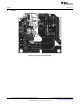
To use the dimming function apply square wave to the PWM test point on the board that has a positive
voltage w.r.t. GND. When this pin is pulled high the dimming FET is enabled and the LED turns off. When
it is pulled low the dimming FET is turned off and the LED turns on. A scope plot of PWM dimming is
included in the Typical Performance Characteristics section showing 30kHz dimming at 50% duty cycle.
5 High Current Operation and Component Lifetime
When driving high current LEDs, particularly when PWM dimming, component lifetime may become a
factor. In these cases the input ripple current that the input capacitors are required to withstand can
become large. At lower currents long life ceramic capacitors may be able to handle this ripple current
without a problem. At higher currents more input capacitance may be required. To remain cost effective
this may require putting one or more aluminum electrolytic capacitors in parallel with the ceramic input
capacitors. Since the operational lifetime of LEDs is very long (up to 50,000 hours) the longevity of an
aluminum electrolytic capacitor can become the main factor in the overall system lifetime. The first
consideration for selecting the input capacitors is the RMS ripple current they will be required to handle.
This current is given by Equation 2:
(2)
The parallel combination of the ceramic and aluminum electrolytic input capacitors must be able to handle
this ripple current. The aluminum electrolytic in particular should be able to handle the ripple current
without a significant rise in core temperature. A good rule of thumb is that if the case temperature of the
capacitor is 5°C above the ambient board temperature then the capacitor is not capable of sustaining the
ripple current for its full rated lifetime and a more robust or lower ESR capacitor should be selected.
The other main considerations for aluminum electrolytic capacitor lifetime are the rated lifetime and the
ambient operating temperature. An aluminum electrolytic capacitor comes with a lifetime rating at a given
core temperature, such as 5000 hours at 105°C. As dictated by physics the capacitor lifetime should
double for each 7°C below this temperature the capacitor operates at and should halve for each 7°C
above this temperature the capacitor operates at. A good quality aluminum electrolytic capacitor will also
have a core temperature of approximately 3°C to 5°C above the ambient temperature at rated RMS
operating current. So as an example, a capacitor rated for 5,000 hours at 105°C that is operating in an
ambient environment of 85°C will have a core temperature of approximately 90°C at full rated RMS
operating current. In this case the expected operating lifetime of the capacitor will be approximately just
over 20,000 hours. The actual lifetime (Life
ACTUAL
) can be found using Equation 3:
(3)
Where Life
RATED
is the rated lifetime at the rated core temperature T
CORE
. For example, if the ambient
temperature is 85°C the core temperature is 85°C + 5°C = 90°C. (105°C - 90°C)/7°C = 2.143. 2^2.413 =
4.417. So the expected lifetime is 5,000*4.417 = 22,085 hours. Long life capacitors are recommended for
LED applications and are available with ratings of up to 20,000 hours or more at 105°C.
2
AN-1793 LM3433 4A to 20A LED Driver Evaluation Board SNVA327B–March 2008–Revised May 2013
Submit Documentation Feedback
Copyright © 2008–2013, Texas Instruments Incorporated