
User manual


LED String Options
www.ti.com
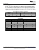
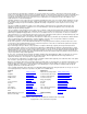
5 LED String Options
Table 2 and Table 3 give the required component changes for driving LED arrays other than the default.
The values shown assume a typical LED Vf of 3.2V at 140mA. These tables are designed for simplicity
and ease of modification, not optimum performance. Therefore, any of the changes listed below will result
in a lower maximum contrast ratio as compared to the default LED array. For optimum performance, all
component values should be reviewed. R5 in the tables refers to the sum of R5a and R5b shown on the
schematic. For the best performance, R5 can be manually adjusted for the specific input voltage, dimming
frequency, and LED current of each application.
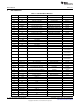
Table 2. LED Current Settings (nc = no change)
LED current R7 R8 R5
160mA 78.7k 13k nc
130mA 100k 13k 17.4k
115mA 115k 13k 18.7k
100mA 93.1k 9.09k 20k
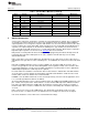
Table 3. LED Array Options at 140mA Setting
(nc = no change)
2 Strings
# of LEDs R19 R3 R5 R6
6 432k 80m 24.9k 43.2k
7 499k 90m 28.7k 26.7k
8 nc 70m 30.1k 23.2k
3 Strings
6 432k nc 28k 43.2k
7 499k nc 24.3k nc
8 nc nc 20k nc
9 634k nc 19.1k 30.1k
4 Strings
6 432k nc 19.1k 43.2k
7 499k nc 16.9k nc
9 634k 40m 14.3k nc
6
AN-1764 LM3431 Evaluation Board SNVA309A–January 2008–Revised May 2013
Submit Documentation Feedback
Copyright © 2008–2013, Texas Instruments Incorporated