
User manual


VA
VA
VC3
VC2
VC1 VC4 GND
THM
board outline
8-pin header
Before Powering Up
www.ti.com
Any dimming frequency between 180Hz and 20kHz can be used in either digital or analog dimming control
mode. However the default schematic is not designed for dimming frequencies above 1kHz.Once the
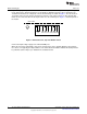
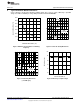
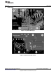
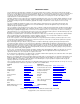
evaluation board has been configured, connect the LED strings as shown in Figure 2. The first anode of
each string connects to the VA post and the last cathode of each string connects to VC1 through VC4.
LEDs can be connected either via the 8-pin header or to the terminal posts. Figure 1 shows the pinout of
the header.
Figure 1. LED Connection, Top View Header Pinout
Connect the input voltage supply to the VIN and GND posts.
When all connections and polarities have been verified, power can be applied. When the input voltage
rises above 7.7V typically, the EN pin will cross the UVLO threshold and the LM3431 will startup. EN can
be pulled low (via the EN post) to shutdown the evaluation board.
2
AN-1764 LM3431 Evaluation Board SNVA309A–January 2008–Revised May 2013
Submit Documentation Feedback
Copyright © 2008–2013, Texas Instruments Incorporated