
User manual

C7 = 1 nF
R10 = 35.7 k:
2525
=
35.7 k: x 1 nF
f
SW
=
R10 x C7
= 700 kHz
2525
=
700 kHz x 1 nF
= 35.7 k:
R10 =
f
SW
x C7
683.0
D
MAX
===
VV
MININO
-
-
V10V5.31 -
V5.31
V
O
175.0
D
MIN
===
VV
MAXINO
-
-
V26V5.31 -
V5.31
V
O
762.0238.01D1'D
=
-
=
-
=
238.0
D
===
V24V5.31 -
V5.31
V
O
VV
INO
-
:
=
:x
=
x
=
925.2m3259rNr
LEDD
V31.5V5.39VNV
LEDO
=
x
=
x
=
Design Procedure
www.ti.com
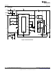
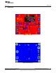
6 Design Procedure
Refer to LM3429 LM3429Q1 N-Channel Controller for Constant Current LED Drivers (SNVS616) data
sheet for design considerations.
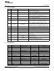
6.1 Specifications
N = 9
V
LED
= 3.5V
r
LED
= 325 mΩ
V
IN
= 24V
V
IN-MIN
= 10V; V
IN-MAX
= 27V
f
SW
= 700 kHz
V
SNS
= 100 mV
I
LED
= 1A
Δi
L-PP
= 250 mA
Δi
LED-PP
= 17 mA
Δv
IN-PP
= 100 mV
I
LIM
= 6A
V
TURN-ON
= 10V; V
HYS
= 3V
V
TURN-OFF
= 60V; V
HYSO
= 15V
6.2 Operating Point
Solve for V
O
and r
D
:
(1)
(2)
Solve for D, D', D
MAX
, and D
MIN
:
(3)
(4)
(5)
(6)
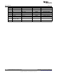
6.3 Switching Frequency
Assume C7 = 1 nF and solve for R10:
(7)
The closest standard resistor is actually 35.7 kΩ therefore the f
SW
is:
(8)
The chosen components from step 2 are:
(9)
6
AN-1986 LM3429 Boost Evaluation Board SNVA404B–July 2009–Revised May 2013
Submit Documentation Feedback
Copyright © 2009–2013, Texas Instruments Incorporated