
User manual

V
IN
(V)
EFFICIENCY (%)
10 15 20 25 30
100
95
90
85
80
User's Guide
SNVA404B–July 2009–Revised May 2013
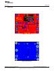
AN-1986 LM3429 Boost Evaluation Board
1 Introduction
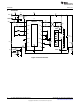
This evaluation board showcases the LM3429 NFET controller used with a boost current regulator. It is
designed to drive 9 to 12 LEDs at a maximum average LED current of 1A from a DC input voltage of 10 to
26V.
The evaluation board showcases most features of the LM3429 including PWM dimming, overvoltage
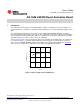
protection and input under-voltage lockout. It also has a right angle connector (J7) which can mate with an
external LED load board allowing for the LEDs to be mounted close to the driver. Alternatively, the LED+
and LED- banana jacks can be used to connect the LED load.
The boost circuit can be easily redesigned for different specifications by changing only a few components
(see Alternate Designs ). Note that design modifications can change the system efficiency for better or
worse. See the LM3429 LM3429Q1 N-Channel Controller for Constant Current LED Drivers (SNVS616)
data sheet for a comprehensive explanation of the device and application information.
Figure 1. Efficiency with 9 Series LEDS AT 1A
All trademarks are the property of their respective owners.
1
SNVA404B–July 2009–Revised May 2013 AN-1986 LM3429 Boost Evaluation Board
Submit Documentation Feedback
Copyright © 2009–2013, Texas Instruments Incorporated