
User manual
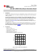


LM3424 Pin Descriptions
www.ti.com
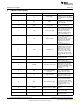
5 LM3424 Pin Descriptions
Pin Name Description Application Information
Bypass with 100 nF capacitor
to GND as close to the device
1 V
IN
Input Voltage
as possible in the circuit board
layout.
Connect to > 2.4V to enable
2 EN Enable the device or to < 0.8V for low
power shutdown.
Connect a capacitor to GND to
3 COMP Compensation
compensate control loop.
Connect a resistor to GND to
set the signal current. Can also
be used to analog dim as
4 CSH Current Sense High
explained in the Thermal
Foldback / Analog Dimming
section of the datasheet.
Connect a resistor to GND to
set the switching frequency.
Can also be used to
5 RT Resistor Timing synchronize external clock as
explained in the Switching
Frequency section of the
datasheet.
Connect a PWM signal for
dimming as detailed in the
PWM Dimming section of the
datasheet and/or a resistor
divider from V
IN
to program
6 nDIM Not DIM input
input under-voltage lockout
(UVLO). Turn-on threshold is
1.24V and hysteresis for turn-
off is provided by 20 µA current
source.
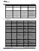
Connect a capacitor to GND to
7 SS Soft-start
extend start-up time.
Connect a resistor to GND to
8 TGAIN Temperature Foldback Gain
set the foldback slope.
Connect a resistor/ thermistor
divider from V
S
to sense the
temperature as explained in
9 TSENSE Temperature Sense Input
the Thermal Foldback / Analog
Dimming section of the
datasheet.
Connect a resistor divider from
Temperature Foldback
10 TREF V
S
to set the temperature
Reference
foldback reference voltage.
2.45V reference for
11 V
S
Voltage Reference temperature foldback circuit
and other external circuitry.
Connect to a resistor divider
from V
O
to program output
over-voltage lockout (OVLO).
12 OVP Over-Voltage Protection Turn-off threshold is 1.24V and
hysteresis for turn-on is
provided by 20 µA current
source.
Connect to gate of dimming
13 DDRV Dimming Gate Drive Output
MosFET.
Connect to DAP to provide
14 GND Ground
proper system GND
Connect to gate of main
15 GATE Gate Drive Output
switching MosFET.
4
AN-1967 LM3424 Buck-Boost Evaluation Board SNVA397A–August 2009–Revised May 2013
Submit Documentation Feedback
Copyright © 2009–2013, Texas Instruments Incorporated