
User manual

2525
=
35.7 k: x 1 nF
f
SW
=
R10 x C7
= 700 kHz
2525
=
700 kHz x 1 nF
= 35.7 k:
R10 =
f
SW
x C7
21V
=
21V + 10V
= 0.677
D
MAX
=
V
O
+ V
IN-MIN
V
O
21V
=
21V + 70V
= 0.231
D
MIN
=
V
O
+ V
IN-MAX
V
O
D' = 1 - D = 1 - 0.467 = 0.533
D =
=
21V
V
O
+ V
IN
21V + 24V
= 0.467
V
O
r
D
= N x r
LED
= 6 x 325 m: = 1.95:
V
O
= N x V
LED
= 6 x 3.5V = 21V
Design Procedure
www.ti.com
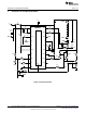
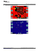
6 Design Procedure
Refer to the LM3421/21Q1/21Q0 LM3423/23Q1/23Q0 N-Ch Controllers for Constant Current LED Drivers
(SNVS574 data sheet for design considerations.
6.1 Specifications
N = 6
V
LED
= 3.5V
r
LED
= 325 mΩ
V
IN
= 24V
V
IN-MIN
= 10V; V
IN-MAX
= 70V
f
SW
= 700 kHz
V
SNS
= 150 mV
I
LED
= 700 mA
Δi
L-PP
= 350 mA
Δi
LED-PP
= 50 mA
Δv
IN-PP
= 100 mV
I
LIM
= 4A
V
TURN-ON
= 10V; V
HYS
= 3.4V
V
TURN-OFF
=44V; V
HYSO
= 10V
6.2 Operating Point
Solve for V
O
and r
D
:
(1)
(2)
Solve for D, D', D
MAX
, and D
MIN
:
(3)
(4)
(5)
(6)
6.3 Switching Frequency
Assume C7 = 1 nF and solve for R10:
(7)
The closest standard resistor is actually 35.7 kΩ therefore the f
SW
is:
(8)
6
AN-2010 LM3423 Buck-Boost 2 Layer Evaluation Board SNVA415C–June 2010–Revised May 2013
Submit Documentation Feedback
Copyright © 2010–2013, Texas Instruments Incorporated