
User manual

R11 = 12.4 k:
R18 = 432 k:
www.ti.com
Design Procedure
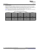
The chosen components from Section 6.13 are:
(54)
6.14 PWM Dimming
The LM3423 Buck-boost Evaluation board is configured to demonstrate PWM dimming of the LEDs. For
best operation, use a PWM signal that has greater than 3V amplitude at a frequency between 120Hz and
5kHz. Apply the PWM signal to the BNC connector (J6) and the inverted signal (seen by the nDIM pin)
can be monitored at TP5.
The output PWM drive signal (DDRV) is level shifted to the floating LED stack using several components
(R19, R17, Q4, Q6, Q7, and D2) and ultimately controls the series dimming FET (Q2). This level shift
adds a several microsecond delay from input to output as seen in the Typical Waveforms section. This
delay, along with the time it takes to slew the LED current from zero to its nominal value, limits the
contrast ratio for a given dimming frequency.
Using the evaluation board (24V input, 21V output), at 5kHz dimming frequency the best case contrast
ratio is approximately 40:1, but at 200Hz the same system is more like 1000:1 ratio. In general, contrast
ratios much above 2000:1 are not possible for any operating point using the LM3423 buck-boost
evaluation board.
6.15 Fault and LED Current Monitoring
The LM3423 has a fault detection flag in the form of an open-drain NFET at the FLT pin. Using the
external pull-up resistor (R14) to VIN, the fault status can be monitored at the FLT pin (high = fault). The
fault timer interval is set with the capacitor (C10) from TIMR to GND (10nF yields roughly 1ms). If a fault is
detected that exceeds the programmed timer interval, such as an output over-voltage condition, the FLT
pin transitions from high to low and internally GATE and DDRV are latched off. To reset the device once
the fault is removed, either the input power must be cycled or the EN pin must be toggled.
This can be tested directly with the evaluation board by opening the LED load. An OVP fault will occur
which disables GATE and DDRV. Then if the LEDs are reconnected, the EN pin jumper (J3) can be
removed and reinserted to restart normal operation of the LM3423.
The LED status flag (LRDY) can be seen by monitoring TP4. LRDY is also an open-drain NFET
connection which has an external pull-up resistor (R15) to V
IN
. If the LED current is in regulation the
voltage at TP4 will be high, but when it falls out of regulation the NFET turns on and pulls TP4 low. The
LM3423 datasheet lists all of the conditions that affect LRDY, FLT, and TIMR.
11
SNVA415C–June 2010–Revised May 2013 AN-2010 LM3423 Buck-Boost 2 Layer Evaluation Board
Submit Documentation Feedback
Copyright © 2010–2013, Texas Instruments Incorporated