
User manual

200
180
160
140
120
100
80
60
40
20
0
0 10 20 30 40 50 60 70 80 90 100
DUTY CYCLE (%)
I
LED
(mA)
1 kHz
500 Hz
100 Hz
DUTY CYCLE (%)
I
LED
(mA)
200
180
160
140
120
100
80
60
40
20
0
0 10 20 30 40 50 60 70 80 90 100
100 Hz
500 Hz
1 kHz
www.ti.com
Over-Voltage Protection
4 Over-Voltage Protection
The evaluation board includes over-voltage protection (OVP) circuitry, in the combination of zener diode
D4 and resistor R3, to protect the LM3410 device in a situation where the output load is suddenly
removed from the rest of the converter (i.e. an LED goes open). A header (J1) on the board allows the
user to activate the OVP function by removing the associated jumper. The switching voltage at the SW pin
will then be clamped to approximately the zener diode voltage of 18 V. Current will then flow through D4,
R3 and sense resistor R1. This generates a voltage greater than 0.190 V at the FB pin that forces the
LM3410’s internal switching power FET to turn off, thereby, preventing an over-voltage condition at the
SW pin and damaging the LM3410.
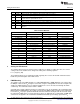
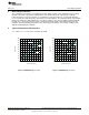
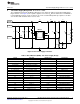
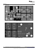
5 Typical Performance Characteristics
T
A
= +25°C, V
OUT
= 11.4 V, unless otherwise specified.
Figure 2. PWM Dimming, V
IN
= 3.3 V Figure 3. PWM Dimming, V
IN
= 5.5 V
3
SNVA410A–April 2010–Revised May 2013 AN-1996 LM3410X 190mA, LED Driver 6-Pin LLP Evaluation Board
Submit Documentation Feedback
Copyright © 2010–2013, Texas Instruments Incorporated