
User manual

P
=
F0.1C4
1
2
3
1
2
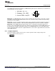
1: No PWM, EN = V
IN
2: Shutdown, EN = GND
3: Internal PWM, using EN
3
J1
www.ti.com
Design Procedure
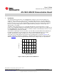
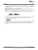
6.11 PWM Dimming / Shutdown Method
The LM3409 demonstration board allows for PWM dimming and low power shutdown to be evaluated. The
desired method is chosen as follows:
Method #1: If no PWM dimming is desired, a jumper should be placed in position 1 (shorts pins 1 and 2)
on header J1. This shorts VIN and EN which ensures the controller is always enabled if an input voltage
greater than 1.74V is applied.
Method #2: Low power shutdown (typically 110µA) can be evaluated by placing the jumper in position 2
(shorts pins 2 and 3) on header J1. This shorts EN and GND which ensures the controller is shutdown.
Method #3: Internal PWM dimming using the EN pin can be evaluated by removing the jumper from
header J1. An external PWM signal can then be applied to the EN terminal to provide PWM dimming. The
R5 potentiometer should be rotated fully clockwise to use PWM dimming across the entire LED current
range of the demonstration board. The Typical Waveforms section shows a typical LED current waveform
during PWM dimming.
6.12 11. Bypass Capacitor
The internal regulator requires at least 1µF of ceramic capacitance with a voltage rating of 16V.
The chosen component from step 11 is:
(33)
9
SNVA391D–May 2009–Revised May 2013 AN-1954 LM3409 Demonstration Board
Submit Documentation Feedback
Copyright © 2009–2013, Texas Instruments Incorporated