
User manual

:
=
k250R5
P
=
F
0.1C6
R5
=
A1 P
=
I
LED
¨
¨
©
§
+
2
L-PP
'i
4Rx
¸
¸
¹
·
A1 P
2
444 mA
¨
©
§
+
200 m:
x
¸
¹
·
A02.1
248 k:
=
R5
Design Procedure
www.ti.com
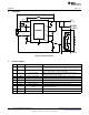
6.10 IADJ Connection Method
The IADJ pin controls the high-side current sense threshold as outlined in the data sheet. The LM3409
demonstration board allows for two methods to be evaluated using the IADJ pin. The desired method is
chosen as follows:
Method #1: Applying an external voltage to the VADJ terminal between 0 and 1.24V linearly scales the
current sense threshold between 0 and 248mV nominally.
Method #2:If no voltage is applied to the VADJ terminal, the internal 5µA current source will bias the
voltage across the external potentiometer (R5). The potentiometer can be used to adjust the current sense
threshold also. It is sized knowing the maximum desired average LED current which is chosen as I
LED
=
1A:
(31)
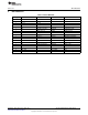
The next highest standard potentiometer of 250kΩ is used. A 0.1µF capacitor (C6) is added from the IADJ
pin to GND in order to eliminate unwanted high frequency noise coupling on the IADJ pin.
The chosen components from step 9 are:
(32)
The Section 7Typical Waveforms shows a typical LED current waveform when analog dimming using the
potentiometer. See the Alternate Designs section for two designs that are optimized to improve analog
dimming range by reducing the switching frequency, increasing the inductance, and adding output
capacitance.
8
AN-1954 LM3409 Demonstration Board SNVA391D–May 2009–Revised May 2013
Submit Documentation Feedback
Copyright © 2009–2013, Texas Instruments Incorporated