
User manual

:
=
:
=
k9.49R3
k98.6R2
=
V1.10
k98.6 :
( )k9.49k98.6V24.1 :+:x
V
ONTURN
=
-
V
ONTURN
=
-
V24.1 ( )R3R2+x
R2
=
:
=
k06.7
:
x
k9.49V24.1
- V24.1V10
=
R2
x
R3V24.1
-
-
V24.1V
ONTURN
1k9.49A22R3V
HYS
x:
=
Px
=
V1.A22
=
P
==
V
R3
HYS
=
:k50
PA22PA22
V1.1
SMC,V60,A5D1o
mA348V
D
x=x mV750 = mW261IP
DD
=
( )
1ID1I
LEDD
-
=
x-
=
¨
¨
©
§
I
LED
x
¸
¸
¹
·
V
IN
Kx
V
O
mA348A02.1
=
x
¸
¸
¹
·
V15
1I
D
-
=
¨
¨
©
§
95.0V24 x
VV
MAXINMAXD
==
--
V42
Q1o 5.7 DPAK,V70,A
mW132m190mARIP
2
DSON
2
RMSTT
=:
x
=
x
=
-
830
11.02A x
+
xx
=
¨
¨
©
§
V15
12
1
95.0V24 x
I
RMST-
2
¸
¸
¹
·
¸
¸
¹
·
¨
¨
©
§
444 mA
1.02A
830 mA
=
I
RMST-
I
LED
x
=
1D
2
x
+
x
¸
¸
¸
¹
·
¸
¸
¹
·
¨
¨
©
§
¨
¨
¨
©
§
12
1
i
L-PP
'
I
LED
I
RMST-
www.ti.com
Design Procedure
(19)
(20)
The chosen component from step 6 is:
(21)
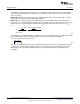
6.8 Re-Circulating Diode
Determine minimum D1 voltage rating and current rating:
(22)
(23)
A 60V, 5A diode is chosen with V
D
= 750mV. Determine P
D
:
(24)
The chosen component from step 7 is:
(25)
6.9 Input Under-Voltage Lockout (UVLO)
Solve for R3:
(26)
The closest 1% tolerance resistor is 49.9 kΩ therefore V
HYS
is:
(27)
Solve for R2:
(28)
The closest 1% tolerance resistor is 6.98 kΩ therefore V
TURN-ON
is:
(29)
The chosen components from step 8 are:
(30)
7
SNVA391D–May 2009–Revised May 2013 AN-1954 LM3409 Demonstration Board
Submit Documentation Feedback
Copyright © 2009–2013, Texas Instruments Incorporated