
User manual

=
mA670
=
A02.1V15 x
95.0V24 x
IDI
LEDT
=
x
=
V
IN
Kx
IV
LEDO
x
V42VV
MAXINMAXT
==
--
F7.4C1 P
=
I
RMSIN-
kHz525A02.1 xx
=
mA483
=
ns651s25.1 xP
tt
OFFON
xfII
SWLEDRMSIN
xx
=
-
2C
MININ
=
x
=
-
F54.3 PC
IN
C
MININ
=
-
= =
F77.1 P
mV720
A02.1 x s25.1 P
v
PPIN
'
-
tI
ONLED
x
1
t
ON
=
1
t
OFF
=
- - ns651
=
s25.1 P
kHz525
f
SW
=
R4
:2.0
I
LED
=
2
444
-
A02.1
=
2.05 :x
V24.1
I
LED
=
R45x
-
2
i
PPL
'
-
V
ADJ
mA
=
R4
V
ADJ
x
-
I5
MAXL
= =
:203.0
V24.1
x5 A22.1
II
LEDMAXL
+
=
-
2
A1
+
=
A22.1
=
2
i
PPL
'
-
444
mA
Design Procedure
www.ti.com
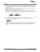
6.4 Average LED Current
Determine I
L-MAX
:
(8)
Assume V
ADJ
= 1.24V and solve for R4:
(9)
The closest 1% tolerance resistor is 0.2 Ω therefore the I
LED
is:
(10)
The chosen component from step 3 is:
(11)
6.5 Output Capacitance
No output capacitance is necessary.
6.6 Input Capacitance
Determine t
ON
:
(12)
Solve for C
IN-MIN
:
(13)
Choose C
IN
:
(14)
Determine I
IN-RMS
:
(15)
The chosen components from step 5 are:
(16)
6.7 P-Channel MOSFET
Determine minimum Q1 voltage rating and current rating:
(17)
(18)
A 70V, 5.7A PFET is chosen with R
DS-ON
= 190mΩ and Q
g
= 20nC. Determine I
T-RMS
and P
T
:
6
AN-1954 LM3409 Demonstration Board SNVA391D–May 2009–Revised May 2013
Submit Documentation Feedback
Copyright © 2009–2013, Texas Instruments Incorporated