
User manual

H22L1 P
=
= =
H22P
444
=
651nsV15 x
L1
tV
OFFO
x
i
PPL
'
-
mA
=
H7.21 P
=
L1
=
i
PPL
'
-
tV
OFFO
x
ns651V15 x
mA450
=
pF470C3
:
=
k4.15R1
t
OFF
f
SW
= =
ns651
=
kHz525
1
-
¸
¹
·
¨
©
§
V2495.0 x
V15
¸
¸
¹
·
¨
¨
©
§
V
O
V
IN
xK
1
-
1lnk4.15pF490t
OFF
-x:x
-
=
¨
¨
©
§
ns651
=
¸
¸
¹
·
V24.1
V15
(C3+20pF)t
OFF
-
=
x R1 x
1
1ln -
¸
¸
¹
·
¨
¨
©
§
V
O
V24.
=
R1
--
1
¸
¸
¹
·
¨
¨
©
§
V
O
xK V
IN
=
R1
:
=
k4.15
x lnpF490 xkHz525
¨
©
§
-
1
V15
¸
¹
·
V24.1
--
1
¨
©
§
¸
¹
·
V15
x V2495.0
-
xx 1lnf(C3 + 20 pF)
SW
¸
¸
¹
·
¨
¨
©
§
V
O
V24.1
www.ti.com
Design Procedure
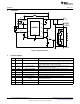
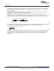
6 Design Procedure
6.1 Specifications
V
IN
= 24V; V
IN-MAX
= 42V
V
O
= 15V
f
SW
= 525kHz
I
LED
= 1A
Δi
LED-PP
= Δi
L-PP
= 450mA
Δv
IN-PP
= 720mV
V
TURN-ON
= 10V; V
HYS
= 1.1V
η = 0.95
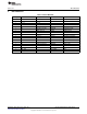
6.2 Nominal Switching Frequency
Assume C3 = 470pF and η = 0.95. Solve for R1:
(1)
The closest 1% tolerance resistor is 15.4 kΩ therefore the actual t
OFF
and target f
SW
are:
(2)
(3)
The chosen components from step 1 are:
(4)
6.3 Inductor Ripple Current
Solve for L1:
(5)
The closest standard inductor value is 22 µH therefore the actual Δi
L-PP
is:
(6)
The chosen component from step 2 is:
(7)
5
SNVA391D–May 2009–Revised May 2013 AN-1954 LM3409 Demonstration Board
Submit Documentation Feedback
Copyright © 2009–2013, Texas Instruments Incorporated