
User manual

I
LED
(A)
V
SW
(V)
70
60
50
40
30
20
10
0
-10
2.0
1.5
1.0
0.5
0.0
-0.5
-1.0
-1.5
-2.0
I
LED
1 Ps/DIV
V
SW
I
LED
(A)
V
SW
(V)
70
60
50
40
30
20
10
0
-10
0.3
0.2
0.1
-2.8E-17
-0.1
-0.2
-0.3
-0.4
-0.5
I
LED
400 ns/DIV
0.0
V
SW
I
LED
(A)
V
EN
(V)
14
12
10
8
6
4
2
0
-2
1.5
1.0
0.5
0.0
-0.5
-1.0
-1.5
-2.0
-2.5
I
LED
10 Ps/DIV
V
EN
I
LED
(A)
V
EN
(V)
7
6
5
4
3
2
1
0
-1
2.1
1.8
1.5
1.2
0.9
0.6
0.3
0.0
-0.3
I
LED
1 Ps/DIV
2 Ps
V
EN
Typical Waveforms
www.ti.com
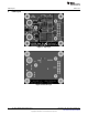
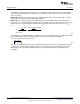
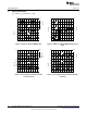
7 Typical Waveforms
T
A
= +25°C, V
IN
= 24V and V
O
= 15V.
Figure 5. 20kHz 50% EN pin PWM dimming Figure 6. 20kHz 50% EN pin PWM dimming (rising
edge)
Figure 7. Analog dimming minimum (R5 fully Figure 8. Analog dimming with maximum (R5 fully
counterclockwise) clockwise)
10
AN-1954 LM3409 Demonstration Board SNVA391D–May 2009–Revised May 2013
Submit Documentation Feedback
Copyright © 2009–2013, Texas Instruments Incorporated