
User manual

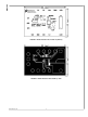
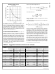
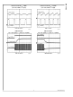

Switching Frequency VS. R
FS
(T
A
= 25°C)
30046707
The LM3407 is internally compensated and requires no ex-
ternal components for feedback compensation. The compo-
nents of this evaluation board are optimized for driving 6
power LEDs with the input voltage between 22V and 30V. If
different conversions are required, such as changes to input
voltage and loading conditions, L1 and RFS may need to be
changed to ensure stable operation.
SELECTION OF INDUCTOR AND DIODE
In order to achieve accurate constant current output, the
LM3407 is required to operate in Continuous Conduction
Mode (CCM) under all operating conditions. In general, the
magnitude of the inductor ripple current should be kept as
small as possible. If the PCB size is not limited, higher induc-
tance values result in better accuracy of the output current.
However, in order to minimize the physical size of the circuit,
an inductor with minimum physical outline should be selected
such that the converter always operates in CCM and the peak
inductor current does not exceed the saturation current limit
of the inductor. The ripple and peak current of the inductor
can be calculated as follows:
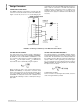
Peak to Peak Inductor Ripple Current:
Peak Inductor Current:
where n is the number of LEDs in a string and V
F
is the forward
voltage of one LED.
The minimum inductance required for the specific application
can be calculated by:
Since the evaluation board is designed to drive a LED array
of 6 LEDs, the default value of the inductor is 33µH to ensure
CCM operation for the input voltage between 22V and 30V
with 1MHz switching frequency. For the applications with dif-
ferent input voltage or number of LEDs, the inductance of the
inductor may have to be changed to maintain accurate output
current. Table 1 shows the suggested inductance of the in-
ductor for 500kHz and 1MHz switching frequency.
The output diode of the evaluation board circuit is selected
depending on the output voltage and current. The diode must
have a rated reverse voltage higher than the input voltage of
the regulator and the peak current rating must be higher than
the expected maximum inductor current. Using a schottky
diode with low forward voltage will decrease power dissipa-
tion and increase conversion efficiency.
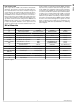
TABLE 1. Suggested Inductance Value of the Inductor
Inductor selection table for f
SW
= 500 kHz, C
OUT
= 4.7 µF (1 µF for 1 LED)
VIN/V Number of LED
1 2 3 4 5 6 7
5 22 µH
10 22 µH 22 µH
15 22 µH 22 µH 22 µH
20 22 µH 33 µH 22 µH 22 µH 22 µH
25 22 µH 33 µH 33 µH 22 µH 22 µH 22 µH
30 22 µH 47 µH 33 µH 33 µH 33 µH 22 µH 22 µH
Inductor selection table for f
SW
= 1 MHz, C
OUT
= 4.7 µF (1 µF for 1 LED)
5 22 µH
10 22 µH 22 µH
15 22 µH 22 µH 22 µH
20 22 µH 22 µH 22 µH 22 µH 22 µH
25 22 µH 22 µH 22 µH 22 µH 22 µH 22 µH
30 22 µH 33 µH 22 µH 22 µH 22 µH 22 µH 22 µH
5 www.national.com
AN-1763