
User manual


Design Procedure
CONNECTING TO LED ARRAY
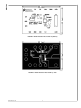
The LM3407 evaluation board features a female 6-pin SIP
connector J1 for board-to-board connection of the LED array.
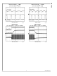
Figure 5 shows the pin-out of J1. To avoid damaging the
components, do not connect the LED array with incorrect po-
larity or alter the connections of the LED array when the
evaluation board is connected to power. It is highly recom-
mended to attach the LED array to a heat sink for heat
dissipation and to apply force ventilation to the LED array as
necessary.
30046705
FIGURE 5. Connecting an LED Array to the LM3407 Evaluation Board
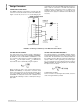
SETTING THE LED CURRENT
The output current of the evaluation board is adjustable by
changing the current setting resistors RISNS1 and RISNS2.
By default, the value of both RISNS1 and RISNS2 is 1.13Ω
at 1% tolerance, which results in a resistance of 0.565Ω. This
value of R
ISNS
sets the output current (I
OUT
) at 350 mA. The
value of R
ISNS
can be calculated by using the equation:
When selecting the value of the current setting resistors
(RISNS1 and RISNS2), it is important to ensure the rated
powers of the resistors are not exceeded. For example, when
I
OUT
is set at 350mA, the total power dissipation on RISNS1
and RISNS2 in steady state is 0.35 mA
2
x 0.565Ω, which
equals 69 mW, indicating a resistor of 1/8W power rating is
appropriate.
SETTING THE SWITCHING FREQUENCY
The switching frequency of the LM3407 evaluation board is
programmable by adjusting the value of the frequency setting
resistor RFS. The default value of the RFS pre-installed on
the evaluation board is 40.2 kΩ, at which the switching fre-
quency is 1MHz. In order to guarantee good current regula-
tion, it is suggested to set the switching frequency between
300KHz and 1MHz. The switching frequency is calculated by
the expression shown below:
for 40kΩ ≤ RFS ≤ 150 kΩ
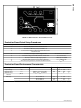
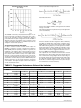
For the convenience of selecting the value of RFS, a selection
chart of f
SW
against RFS is provided:
www.national.com 4
AN-1763