
User manual


30046704
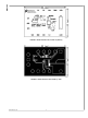
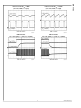
FIGURE 4. LM3407 Evaluation Board PCB Bottom View
Evaluation Board Quick Setup Procedures
Step Procedure Notes
1 Remove all jumpers on the evaluation board.
2 Connect the LED array of 6 power LEDs to J1.
3 Connect Power Supply output to the VIN terminal of the
evaluation board.
4 Set the power supply output voltage to 24V. V
IN
should not exceed 30V
6 Check the voltage of the VCC terminal of the board. V
CC
= 4.5V ± 8%
7 Short pin 1 and 2 of J3 by using a jumper. LEDs fully turned ON
8 Check the LED current (I
OUT
) by using an ammeter. I
OUT
= 350mA ± 6%
9 Short J2 by using a jumper to check the shutdown function. I
OUT
= 0
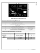
Evaluation Board Performance Characteristic
Description Symbol Condition Min Typ Max Unit
Input Voltage V
IN
22 24 30 V
Output Current I
OUT
DIM pin connected to VCC 330 350 370 mA
Output Current
Variation
|ΔI
OUT
|
All V
IN
and I
OUT
Conditions 6 %
Efficiency No. of LED = 6 93 96 %
No. of LED = 4 90 95 %
No. of LED = 2 85 92 %
3 www.national.com
AN-1763