LM3407 Application Note 1763 LM3407 Evaluation Board Reference Design Literature Number: SNVA308A
National Semiconductor Application Note 1763 SH Wong January 21, 2009 Introduction with an external 1% thick film current setting resistor. The converter features a DIM pin which accepts standard logic pulses for controlling the brightness of the LED array, making the LM3407 ideal for use as a precision power LED driver or constant current source.
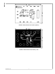
AN-1763 30046702 FIGURE 2. LM3407 Evaluation Board PCB Top Overlay 30046703 FIGURE 3. LM3407 Evaluation Board PCB Top View www.national.
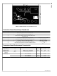
AN-1763 30046704 FIGURE 4. LM3407 Evaluation Board PCB Bottom View Evaluation Board Quick Setup Procedures Step Procedure 1 Remove all jumpers on the evaluation board. Notes 2 Connect the LED array of 6 power LEDs to J1. 3 Connect Power Supply output to the VIN terminal of the evaluation board. 4 Set the power supply output voltage to 24V. 6 Check the voltage of the VCC terminal of the board. VCC = 4.5V ± 8% 7 Short pin 1 and 2 of J3 by using a jumper.
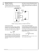
AN-1763 components, do not connect the LED array with incorrect polarity or alter the connections of the LED array when the evaluation board is connected to power. It is highly recommended to attach the LED array to a heat sink for heat dissipation and to apply force ventilation to the LED array as necessary. Design Procedure CONNECTING TO LED ARRAY The LM3407 evaluation board features a female 6-pin SIP connector J1 for board-to-board connection of the LED array. Figure 5 shows the pin-out of J1.
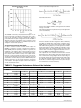
AN-1763 Switching Frequency VS. RFS (TA = 25°C) Peak to Peak Inductor Ripple Current: Peak Inductor Current: where n is the number of LEDs in a string and VF is the forward voltage of one LED. The minimum inductance required for the specific application can be calculated by: 30046707 The LM3407 is internally compensated and requires no external components for feedback compensation. The components of this evaluation board are optimized for driving 6 power LEDs with the input voltage between 22V and 30V.
AN-1763 should have a logic low of 1V maximum and logic high of 2V minimum. The DIM terminal is internally pulled down to ground by a 400 kΩ resistor, which should be connected to either logic high or low and should not be left open. In steady state, the expression of the average LED driving current is: LED DIMMING There are two ways to disable the current output (IOUT) of the evaluation board circuit.
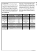
Bill of Materials Designation Description Package Manufacture Part # Vendor U1 LED Driver IC, LM3407 eMSOP-8 LM3407 NSC L1 Inductor 33µH 0.58A 4.0 x 4.0 x 1.8 (mm) LPS4018-333ML Coilcraft * Inductor 33µH 0.56A 4.8 x 4.3 x 3.5 (mm) CR43NP-330K Sumida D1 Schottky Diode 40V 1.0A DO-214AC (SMA) SS14 Vishay CIN, COUT Cap MLCC 50V 4.7µF X7R 1210 GRM32ER71H475K88L Murata CVCC Cap MLCC 10V 1.0µF X5R 0805 GRM188R61A105KA61D Murata RISNS1, RISNS2 Chip Resistor 1.
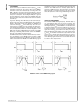
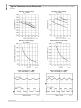
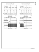
AN-1763 Typical Performance and Waveforms All curves and waveforms taken at TA = 25°C unless otherwise specified. Efficiency vs Input Voltage (TA = -40°C) Efficiency vs Input Voltage (TA = 25°C) 30046713 30046714 Efficiency vs Input Voltage (TA = 125°C) Output Current vs Input Voltage (TA = 25°C) 30046715 30046716 Inductor Current @ fSW = 1MHz (VIN = 12V, 2LEDs, L = 33µH) Inductor Current @ fSW = 500kHz (VIN = 12V, 2LEDs, L = 33µH) 30046718 www.national.
AN-1763 Inductor Current @ fSW = 1MHz (VIN = 24V, 2LEDs, L = 33µH) Inductor Current @ fSW = 500kHz (VIN = 24V, 2LEDs, L = 33µH) 30046720 30046721 DIM Pin Enable (VIN = 24V, 2LEDs, L = 33µH, fSW = 500kHz) DIM Pin Disable (VIN = 24V, 2LEDs, L = 33µH, fSW = 500kHz) 30046723 30046722 9 www.national.
LM3407 Evaluation Board Reference Design Notes For more National Semiconductor product information and proven design tools, visit the following Web sites at: Products Design Support Amplifiers www.national.com/amplifiers WEBENCH® Tools www.national.com/webench Audio www.national.com/audio App Notes www.national.com/appnotes Clock and Timing www.national.com/timing Reference Designs www.national.com/refdesigns Data Converters www.national.com/adc Samples www.national.
IMPORTANT NOTICE Texas Instruments Incorporated and its subsidiaries (TI) reserve the right to make corrections, modifications, enhancements, improvements, and other changes to its products and services at any time and to discontinue any product or service without notice. Customers should obtain the latest relevant information before placing orders and should verify that such information is current and complete.