
User manual

0 10 20 30 40 50 60 70 80 90 100
0
50
100
150
200
250
350
I
LED
(A)
DUTY CYCLE (%)
300
f
DIM
= 25 kHz
f
DIM
= 5 kHz
f
DIM
= 500 Hz
-6.0
0.5 7.0 13.5 20.0
TIME (Ps)
-2.0
4.0
10.0
16.0
22.0
28.0
34.0
V
SW
(V)
0.5
0.4
0.2
0.1
-0.1
-0.3
-0.4
I
LED
(
A
)
f
SW
= 650 kHz
I
LED
(A)
V
SW
(V)
V
DIM
(V)
f
SW
= 75 kHz
0.2V
V
IN
x K
t
OFF
= t
ON
- 1
V
OUT
V
IN
x K
t
OFF
= t
ON
- 1
Linearity with Fast Dimming
www.ti.com
(46)
t
OFF
equation then becomes:
(47)
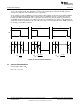
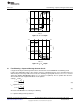
when Q2 shunt MOSFET is OFF during fast dimming.
This is an added benefit due to the fact that t
OFF
is greatly increased, and therefore the switching
frequency is decreased, which leads to improved efficiency (see Figure 16). Inductor L1 still remains
charged, and as soon as Q4 turns off current flows through the LED string.
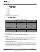
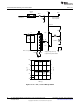
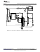
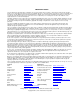
Figure 15. Improved Avg I
LED
Circuit + Fast Dimming
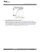
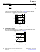
17 Linearity with Fast Dimming
Once the delays and rise/fall times have been greatly reduced, linear average current vs, duty cycle (D
DIM
)
can be achieved at very high dimming frequencies (f
DIM
) (see Figure 17).
Figure 16. Linearity With Fast Dimming
22
AN-1839 LM3402/LM3404 Fast Dimming and True Constant LED Current SNVA342E–July 2008–Revised April 2013
Evaluation Board
Submit Documentation Feedback
Copyright © 2008–2013, Texas Instruments Incorporated