
User manual

V
IN
- 0.2V
R
ON
t
ON
= k x
V
IN
- V
OUT
R
ON
t
ON
= k x
TIME (ns)
-100
-60 -20 20 60
100
V
DIM
(V)
I
LED
(
A
)
-0.20
0.20
0.60
1.00
0.0
4.0
8.0
12.0
I
LED
V
DIM
36 ns
TIME (ns)
-100
-60 -20 20 60
100
V
DIM
(V)
I
LED
(
A
)
-0.1
0.2
0.5
0.8
1.1
-1
3
7
11
I
LED
V
DIM
40 ns
www.ti.com
Fast Dimming + Improved Average Current Circuit
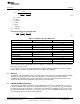
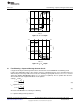
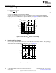
Figure 13. t
D
+ t
SU
Graph
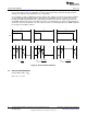
Figure 14. t
D
+ t
SD
Graph
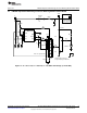
16 Fast Dimming + Improved Average Current Circuit
Using both the Improved Average LED current circuit and the external MOSFET fast dimming circuit
together has additional benefits. If R
ON
and the converter's switching frequency (f
SW
) is determined and set
with the improved average LED current circuit, the switching frequency will decrease once V
OUT
is shorted
during fast dimming. With MOSFET Q4 on, V
OUT
is equal to V
FB
(200 mV). The t
ON
equation then becomes
almost identical to the original unmodified circuit equation.
Setting t
ON
and R
ON
:
(44)
t
ON
equation becomes:
(45)
when Q4 shunt MOSFET is on during fast dimming.
t
OFF
equation during normal operation is:
21
SNVA342E–July 2008–Revised April 2013 AN-1839 LM3402/LM3404 Fast Dimming and True Constant LED Current
Evaluation Board
Submit Documentation Feedback
Copyright © 2008–2013, Texas Instruments Incorporated